


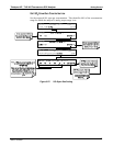

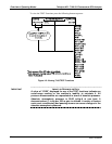
Teledyne API - T100 UV Fluorescence SO2 Analyzer Overview of Operating Modes
83
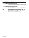
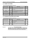
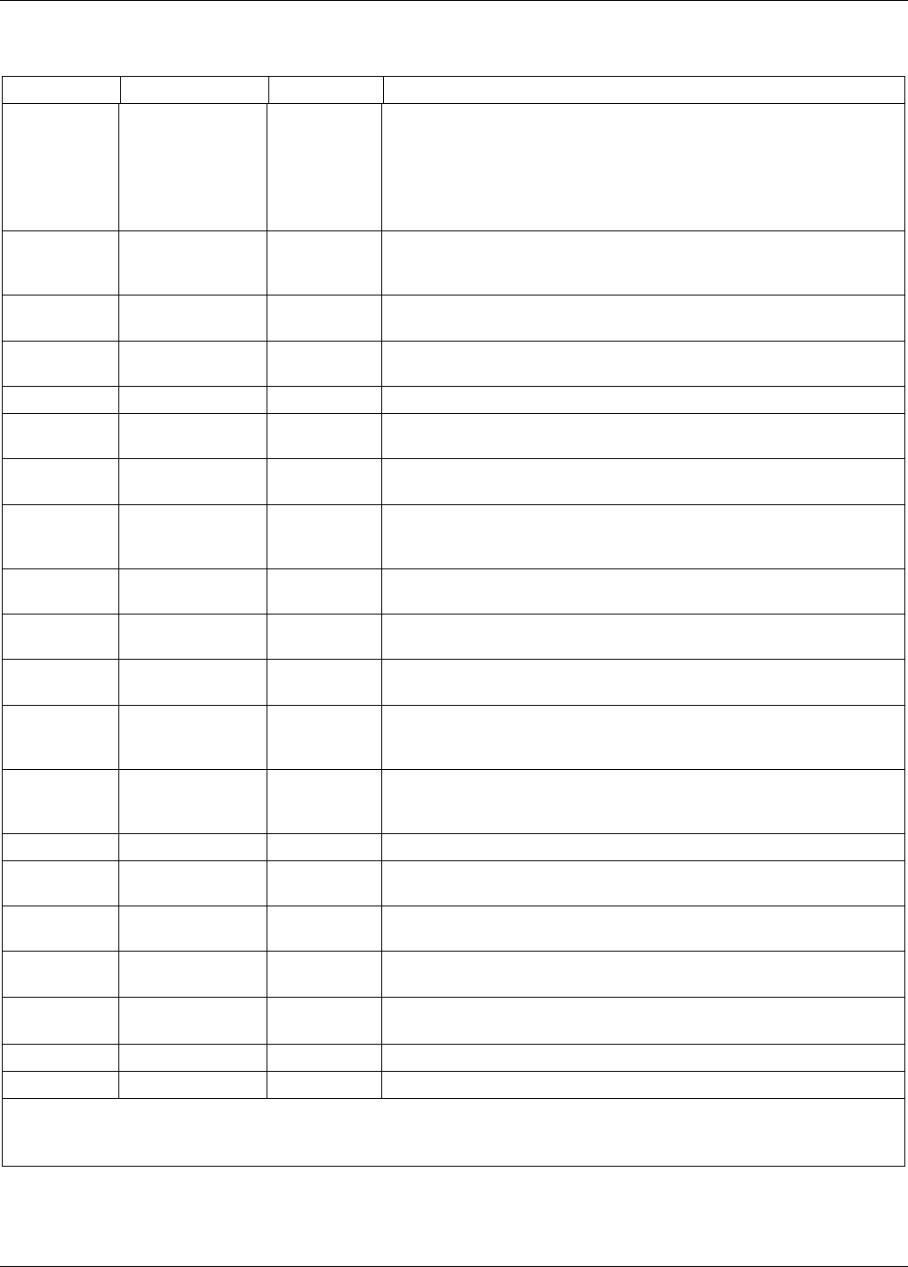
Table 4-2: Test Functions Defined
DISPLAY PARAMETER UNITS DESCRIPTION
RANGE RANGE
- -
RANGE1
RANGE2
PPB, PPM,
UGM & MGM
The Full Scale limit at which the reporting range of the analyzer’s
ANALOG OUTPUTS is currently set.
THIS IS NOT the Physical Range of the instrument. Refer to Section
5.4 for more information.
If DUAL or AUTO
Range modes have been selected, two RANGE
functions will appear, one for each range.
STABIL
STABILITY mV
Standard deviation of SO
2
Concentration readings. Data points are
recorded every ten seconds. The calculation uses the last 25 data
points.
PRES
SAMPLE
PRESSURE
in-Hg-A
The current pressure of the sample gas as it enters the sample
chamber, measured between the SO
2
and Auto-Zero valves.
SAMP FL
SAMPLE FLOW
cm³/min
(cc/m)
The flow rate of the sample gas through the sample chamber. This
value is not measured but calculated from the sample pressure.
PMT
PMT Signal mV The raw output voltage of the PMT.
NORM PMT
NORMALIZED
PMT Signal
mV
The output voltage of the PMT after normalization for offset and
temperature/pressure compensation (if activated).
UV LAMP
Source UV Lamp
Intensity
mV The output voltage of the UV reference detector.
LAMP
RATIO
UV Source lamp
ratio
%
The current output of the UV reference detector divided by the reading
stored in the CPU’s memory from the last time a UV Lamp calibration
was performed.
STR. LGT
Stray Light ppb
The offset due to stray light recorded by the CPU during the last zero-
point calibration performed.
DRK PMT
Dark PMT mV
The PMT output reading recorded the last time the UV source lamp
shutter was closed.
DRK LMP
Dark UV Source
Lamp
mV
The UV reference detector output reading recorded the last time the
UV source lamp shutter was closed.
SLOPE SO
2
measurement
Slope
-
The sensitivity of the instrument as calculated during the last
calibration activity. The slope parameter is used to set the span
calibration point of the analyzer.
OFFSET SO
2
measurement
Offset
mV
The overall offset of the instrument as calculated during the last
calibration activity. The offset parameter is used to set the zero point
of the analyzer response.
HVPS
HVPS V The PMT high voltage power supply.
RCELL
TEMP
SAMPLE
CHAMBER TEMP
°C The current temperature of the sample chamber.
BOX TEMP
BOX
TEMPERATURE
°C The ambient temperature of the inside of the analyzer case.
PMT TEMP
PMT
TEMPERATURE
°C The current temperature of the PMT.
IZS TEMP
1
IZS
TEMPERATURE
1
°C
The current temperature of the internal zero/span option. Only
appears when IZS option is enabled.
TEST
2
TEST SIGNAL
2
mV Signal of a user-defined test function on output channel A4.
TIME
CLOCK TIME hh:mm:ss The current day time for DAS records and calibration events.
1
Only appears if Internal Gas Span Generator option is installed.
2
Only appears if analog output A3 is actively reporting a test function.
06807C DCN6650