


Teledyne API - T100 UV Fluorescence SO2 Analyzer Getting Started
35
3.2. INSTRUMENT LAYOUT
Instrument layout includes front panel and display, rear panel connectors, and internal
chassis layout.
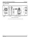
3.2.1. FRONT PANEL
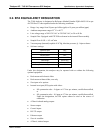
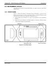
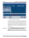
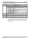
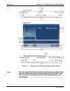
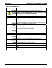
Figure 3-1 shows the analyzer’s front panel layout, followed by a close-up of the
display screen in Figure 3-2, which is described in Table 3-2. The two USB ports on the
front panel are provided for the connection of periphe
ral devices:
plug-in mouse (not included) to be used as an alternative to the touchscreen
interface
thumb drive (not included) to download updates to instruction software (contact
TAPI Technical Support for information).
Figure 3-1: Front Panel Layout
06807C DCN6650