


Teledyne API - T100 UV Fluorescence SO2 Analyzer Principles of Operation
289
concentrations of some or all of these may be very high, specific steps MUST be taken
to remove them from the sample gas before it enters the analyzer.
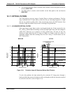
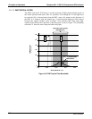
13.1.9.5. LIGHT POLLUTION
Because T100 measures light as a means of calculating the amount of SO
2
present,
obviously stray light can be a significant interfering factor. The T100 removes this
interference source in several ways.
The sample chamber is designed to be completely light tight to light from sources
other than the excitation UV source lamp.
All pneumatic tubing leading into the sample chamber is completely opaque in order
to prevent light from being piped into the chamber by the tubing walls.
The optical filters discussed in Section 13.1.7; remove UV with wavelengths
extraneous to the excitation and deca
y
of SO
2
/SO
2
*.
Most importantly, during instrument calibration the difference between the value of
the most recently recorded PMT offset (refer to Section 13.1.6) and the PMT output
while
measur
ing zero gas (calibration gas devoid of SO
2
) is recorded as the test
function OFFSET. This OFFSET value is used during the calculation of the SO
2
concentration.
Since this offset is assumed to be due to stray light present in the sample chamber is also
multiplied by the SLOPE and recorded as the function STR. LGT. Both OFFSET
& STR. LGT are viewable via the front panel (refer to Section 4.1.1).
13.2. OXYGEN (O
2
) SENSOR PRINCIPLES OF OPERATION
The O
2
sensor applies paramagnetics to determine the concentration of oxygen in a
sample gas drawn through the instrument.
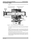
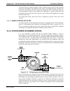
13.2.1. PARAMAGNETIC MEASUREMENT OF O
2
The oxygen sensor used in the T100 utilizes the fact that oxygen is attracted into strong
magnetic field while most other gases are not, to obtain fast, accurate oxygen
measurements.
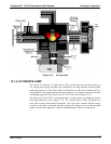
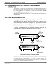
The sensor’s core is made up of two nitrogen filled glass spheres, which are mounted on
a rotating suspension within a magnetic field (refer to Figure 13-7). A mirror is
m
ounted centrally
on the suspension and light is shone onto the mirror that reflects the
light onto a pair of photocells. The signal generated by the photocells is passed to a
feedback loop, which outputs a current to a wire winding (in effect, a small DC electric
motor) mounted on the suspended mirror.
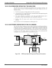
Oxygen from the sample stream is attracted into the magnetic field displacing the
nitrogen filled spheres and causing the suspended mirror to rotate. Therefore, the
amount of light reflected onto the photocells and therefore the output levels of the
photocells. The feedback loop increases the amount of current fed into the winding in
order to move the mirror back into its original position. The more O
2
present, the more
the mirror moves and the more current is fed into the winding by the feedback control
loop.
A sensor measures the amount of current generated by the feedback control loop which
is directly proportional to the concentration of oxygen within the sample gas mixture.
06807C DCN6650