


Teledyne API - T100 UV Fluorescence SO2 Analyzer Troubleshooting & Service
275
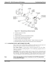
13. Turn the gain adjustment potentiometer clockwise to its maximum setting.
14. Set the front panel display to show STABIL (refer to Section 4.1.1).
15. Feed span g
as into the analyzer.
16. Wait until the STABIL value is below 0.5 ppb.
IMPORTANT
IMPACT ON READINGS OR DATA
Use a span gas equal to 80% of the reporting range.
Example: for a reporting range of 500 ppb, use a span gas of 400 ppb.
17. Scroll to the OFFSET function and record the value.
18. Scroll to the NORM PMT value.
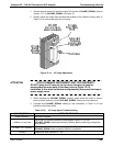
ATTENTION
COULD DAMAGE INSTRUMENT AND VOID WARRANTY
Do not overload the PMT by accidentally setting both adjustment
switches to their maximum setting. This can cause permanent damage
to the PMT.
19. Determine the target NORM PMT value according to the following formulas.
If the reporting range is set for 2,000 ppb (the instrument will be using the 2,000
ppb physical range):
Target NORM PMT =
(2 x span gas concentration) + OFFSET
If the reporting range is set for 2,001 ppb(the instrument will be using the 20,000
ppb physical range):
Target NORM PMT =
(0.181 x span gas concentration) + OFFSET
EXAMPLE: If the OFFSET IS 33 mV, the Reporting Range is 500 ppb, the
span gas should be 400 ppb and the calculation would be:
Target NORM PMT = (2 x 400) + 33 mV
Target NORM PMT =
833 mV
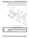
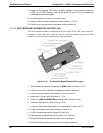
20. Set the HVPS coarse adjustment switch to the lowest setting that will give you more
than the target NORM PMT signal from Step 16.
The coarse adjustment typically increments the NORM PMT signal in 100-300 mV
steps.
21. Adjust the HVPS fine adjustment such that the NORM PMT value is at or just above
the target NORM PMT signal from Step 16.
22. Continue adjusting the both the coarse and fine switches until norm PMT is as close
to (but not below) the target NORM PMT signal from Step 16.
23. Adjust gain adjustment potentiometer until the NORM PMT value is ±10 mV of the
target level from Step 16.
24. Perform span and zero-point calibrations (refer to Section 9) to normalize the sensor
respon
se to its ne
w PMT sensitivity.
25. Review the slope and offset values, and compare them to the values in Table 9-5.
06807C DCN6650