


Teledyne API - T100 UV Fluorescence SO2 Analyzer Principles of Operation
285
The reference detector offset is stored as and viewable via the front panel as the test
function DRK LMP.
The PMT offset is stored as and viewable via the front panel as the test function
DRK PMT.
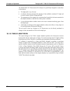
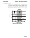
13.1.7. OPTICAL FILTERS
The T100 analyzer uses two stages of optical filters to enhance performance. The first
stage conditions the UV light used to excite the SO
2
by removing frequencies of light
that are not needed to produce SO
2
*. The second stage protects the PMT detector from
reacting to light not produced by the SO
2
* returning to its ground state.
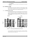
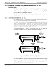
13.1.7.1. UV SOURCE OPTICAL FILTER
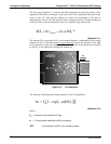
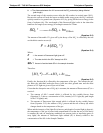
Zinc-vapor lamps output light at other wavelengths beside the 214nm required for the
SO
2
SO
2
* transformation including a relatively bright light of the same wavelength at
which SO
2
* fluoresces as it returns to its SO
2
ground state (330 nm). In fact, the
intensity of light emitted by the UV lamp at 330nm is so bright, nearly five orders of
magnitude brighter than that resulting from the SO
2
* decay, it would drown out the
SO
2
* fluorescence.
LAMP OUTPUT
(Arbitrary Untis)
10
5
10
4
10
2
202.5
307.6
481.1
10
3
10
1
1
100 200 300 400 500
WAVELENGTH (nm)
0
213.9
330.3
275.6
SO
2
*
Fluorescent
Spectrum
LAMP OUTPUT
(Arbitrary Untis)
10
5
10
4
10
2
10
3
10
1
1
100
200
300 400
500
WAVELENGTH (nm)
0
213.9
330.3
SO
2
* FLUORESCENT
SPECTRUM
UV SOURCE OPTICAL FILTER
BANDWIDTH
BEFORE AFTER
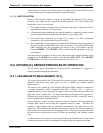
Figure 13-4: Excitation Lamp UV Spectrum Before/After Filtration
To solve this problem, the light emitted by the excitation UV lamp passes through a
band pass filter that screens out photons with wavelengths outside the spectrum required
to excite SO
2
into SO
2
* (refer to Figure 13-4).
06807C DCN6650