


Teledyne API - T100 UV Fluorescence SO2 Analyzer Troubleshooting & Service
239
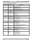
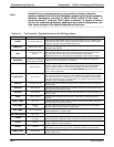
Warning Message Fault Condition Possible Causes
SAMPLE PRES WARN
Sample Pressure is <10 in-
Hg or
> 35 in-Hg
1
If sample pressure is < 10 in-hg:
o Blocked particulate filter
o Blocked sample inlet/gas line
o Failed pressure sensor/circuitry
If sample pressure is > 35 in-hg:
o Blocked vent line on pressurized sample/zero/span gas supply
o Bad pressure sensor/circuitry
SYSTEM RESET
The computer has
rebooted.
This message occurs at power on.
If it is confirmed that power has not been interrupted:
Failed +5 VDC power,
Fatal error caused software to restart
Loose connector/wiring
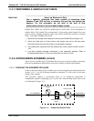
UV LAMP WARNING
The UV lamp intensity is <
600mV or > 4995 mV
UV lamp is bad
Reference detector is bad or out of adjustment.
Mother board analog sensor input circuitry has failed.
Fogged or damaged lenses/filters in UV light path
A/D converter circuitry failure
Light leak in reaction cell
Shutter solenoid stuck closed
1
Normally 29.92 in-Hg at sea level decreasing at 1 in-Hg per 1000 ft of altitude
(with no flow – pump disconnected).
IMPORTANT
IMPACT ON READINGS OR DATA
A failure of the analyzer’s CPU, motherboard or power supplies can
result in any or ALL of the above messages.
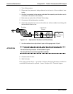
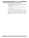
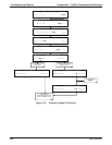
12.1.2. FAULT DIAGNOSIS WITH TEST FUNCTIONS
Besides being useful as predictive diagnostic tools, the TEST functions, viewable from
the front panel, can be used to isolate and identify many operational problems when
combined with a thorough understanding of the analyzer’s principles of operation (refer
to Section 13. We recommend use of the APICOM remote control program (Section 7)
to download, graph and archive TEST data for analy
sis, and long-term monitoring of
diagnostic data.
The acceptable ranges for these test functions are listed in Table A-3 in Appendix A-3.
The actual values for these test functions on checkout at the factory were also listed in
the Final Test and Validation Data Sheet, which was shipped with the instrument.
Values outside the acceptable ranges indicate a failure of one or more of the analyzer’s
subsystems. Functions with values that are within the acceptable range but have
significantly changed from the measurements recorded on the factory data sheet may
also indicate a failure or a maintenance item.
A problem report worksheet has been provided in Appendix C to assist in recording the
value of these test functions. Table 12-2 contains some of the more common causes for
these values t
o
be out of range.
IMPORTANT
IMPACT ON READINGS OR DATA
A value of “XXXX” displayed for any of these TEST functions indicates an
OUT OF RANGE reading.
06807C DCN6650