


Getting Started Teledyne API - T100 UV Fluorescence SO2 Analyzer
62
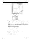
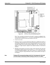
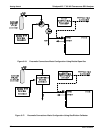
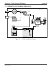
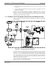
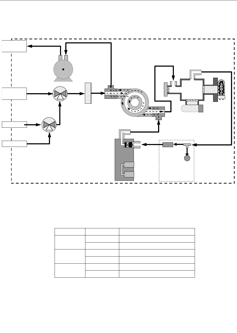
3.3.2.3. PNEUMATIC LAYOUT FOR ZERO/SPAN VALVES OPTION
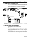
Figure 3-19 shows the internal, pneumatic connections for a T100 with the zero/span
valve option in
stalled.
FLOW
SENSOR
FLOW / PRESSURE
SENSOR PCA
SAMPLE
PRESSURE
SENSOR
VACUUM MANIFOLD
FLOW
CONTROL
ASSY
EXHAUST TO OUTER
LAYER OF KICKER
SAMPLE/CAL
VALVE
SAMPLE GAS
INLET
ZERO AIR INLET
SPAN 1 INLET
ZERO/SPAN
VALVE
SAMPLE FILTER
Chassis
EXHAUST GAS
OUTLET
KICKER EXHAUST
TO PUMP
HYDROCARBON
SCRUBBER
(KICKER)
UV
LAMP
PMT
SAMPLE
CHAMBER
PUMP
NC
NO
COM
NC
NO
COM
Figure 3-19: Pneumatic Layout with Zero/Span Valves Option
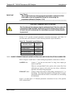
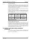
Table 3-10 describes the state of each valve during the analyzer’s various operational
modes.
Table 3-10: Zero/Span and Sample/Cal Valve Operating States
MODE VALVE CONDITION
Sample/Cal Open to SAMPLE inlet
SAMPLE
Zero/Span Open to ZERO AIR inlet
Sample/Cal Open to zero/span inlet
ZERO CAL
Zero/Span Open to ZERO AIR inlet
Sample/Cal Open to zero/span inlet
SPAN CAL
Zero/Span Open to SPAN GAS inlet
The state of the zero/span valves can also be controlled by any of the following means:
manually from the analyzer’s front panel by using the SIGNAL I/O controls
located within the DIAG Menu (refer to Section 5.9.1)
by activating
the instrument’s AutoCal feature (refer to Section 9.8)
06807C DCN6650