


Teledyne API - T100 UV Fluorescence SO2 Analyzer Getting Started
43
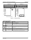
3.3.1.1. CONNECTING POWER
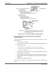
Attach the power cord to the analyzer and plug it into a power outlet capable of carrying
at least 10 Amps of current at your AC voltage and that it is equipped with a functioning
earth ground.
WARNING
ELECTRICAL SHOCK HAZARD
High Voltages are present inside the analyzers case.
Power connection must have functioning ground connection.
Do not defeat the ground wire on power plug.
Power off analyzer before disconnecting or connecting electrical
subassemblies.
Do not operate analyzer with the cover off.
CAUTION
GENERAL SAFETY HAZARD
The T100 analyzer can be configured for both 100-120 V and 220-240 V at
either 50 or 60 Hz.
To avoid damage to your analyzer, ensure that the AC power voltage
matches the voltage indicated on the Analyzer’s model identification label
(refer to Figure 3-4) before plugging the T100 into line power.
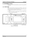
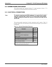
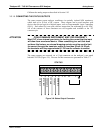
3.3.1.2. CONNECTING ANALOG INPUTS (OPTION)
The Analog In connector is used for connecting external voltage signals from other
instrumentation (such as meteorological instruments) and for logging these signals in the
analyzer’s internal DAS. The input voltage range for each analog input is 1-10 VDC,
and input impedance is nominally 20kΩ in parallel with 0.1µF.
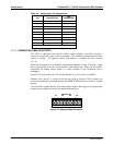
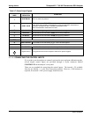
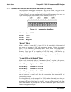
Figure 3-6: Analog In Connector
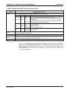
Pin assignments for the Analog In connector are presented in Table 3-5 .
06807C DCN6650