


Principles of Operation Teledyne API - T100 UV Fluorescence SO2 Analyzer
312
WARNING
Should the power circuit breaker trip, correct the condition causing this
situation before turning the analyzer back on.
AC POWER
ENTRANCE
ON/OFF
SWITCH
Pressure
Sensor
Mother
Board
CPU
PS 1 (+5 VDC; ±15 VDC)
PS 2 (+12 VDC)
Chassis
Cooling
Fan
PMT High
Voltage Supply
IZS Option
Permeation
Tube
Heater
PUMP
Temperature
Sensors
Gas Flow
Sensor
Sample
Chamber
Heaters
Sample/Cal
for Z/S and
IZS Valve
Options
KEY
AC POWER
DC POWER
UV Source
Lamp
Power
Su
pp
l
y
PMT
Cooling
Fan
PMT
Preamp
UV Source
Lamp
Shutter
RELAY
BOARD
TEC
Control
PCA
USB
In-Line AC
Configuration
Connector
LVDS
transmitter board
Display
Touchscreen
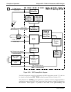
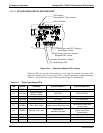
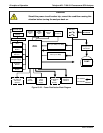
Figure 13-22: Power Distribution Block Diagram
06807C DCN6650