


Troubleshooting & Service Teledyne API - T100 UV Fluorescence SO2 Analyzer
252
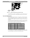
12.6.6. RELAY BOARD
The relay board circuit can most easily be checked by observing the condition of its
status LEDs as described in Section 12.2, and the associated output when toggled on and
off through the SIGNAL I/O function in
the DIAG menu, refer to Section 5.9.1.
If the front panel display re
sponds to button presses and D1 on the relay board is not
flashing, then either the I
2
C connection between the motherboard and the relay
board is bad, or the relay board itself is bad.
If D1 on the relay board is flashing, but toggling an output in the Signal I/O
function menu does not toggle the output’s status LED, the there is a circuit
problem, or possibly a blown driver chip, on the relay board.
If D1 on the Relay board is flashing and the status indicator for the output in
question (heater, valve, etc.) toggles properly using the Signal I/O function, but the
output device does not turn on/off, then the associated device (valve or heater) or its
control device (valve driver, heater relay) is malfunctioning.
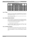
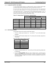
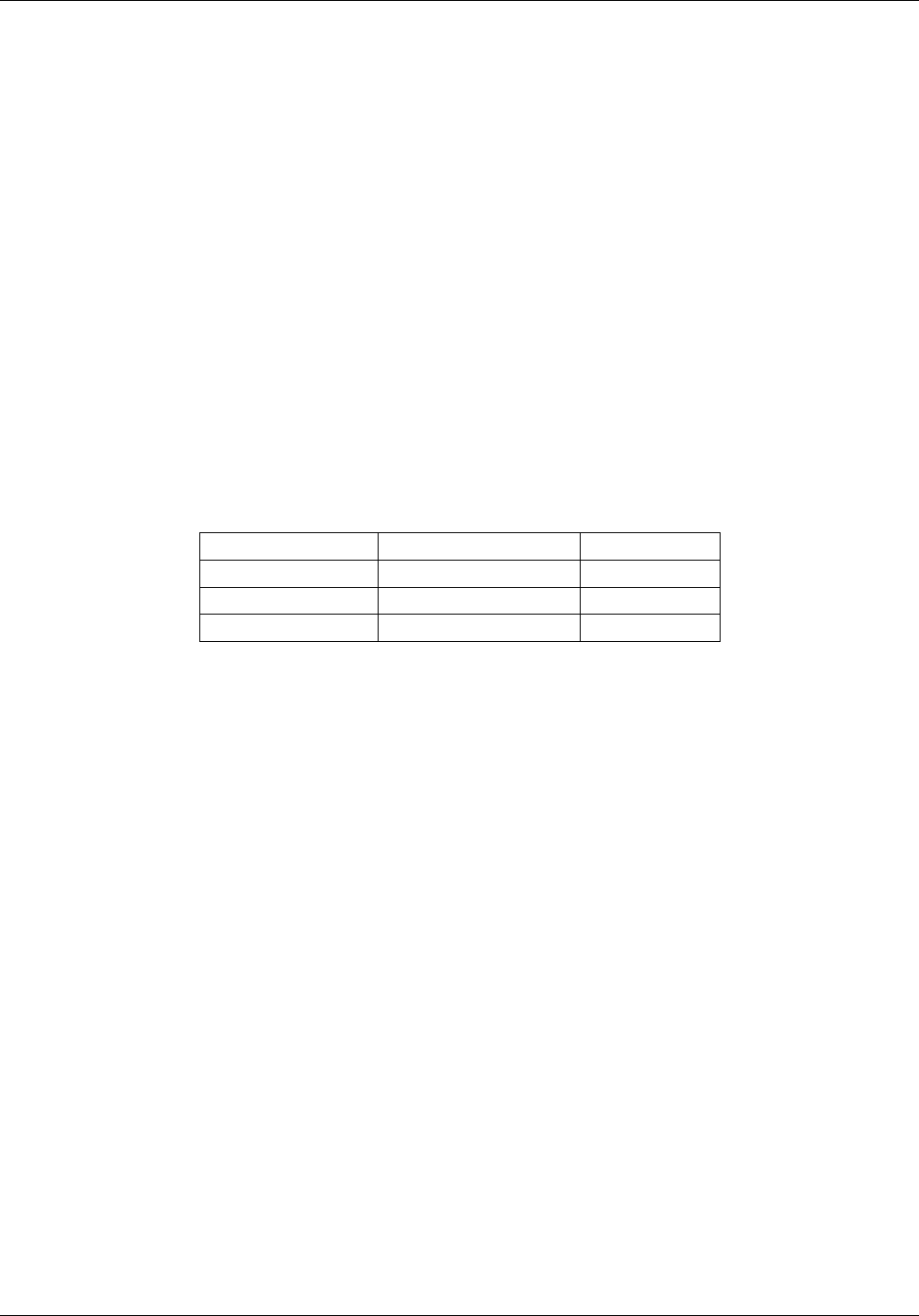
Several of the control devices are in sockets and can easily be replaced. The table below
lists the control device associated with a particular function:
Table 12-6: Relay Board Control Devices
FUNCTION CONTROL DEVICE SOCKETED
Valve0 – Valve3 U5 Yes
Valve4 – Valve7 U6 Yes
All heaters K1-K5 Yes
12.6.7. MOTHERBOARD
12.6.7.1. A/D FUNCTIONS
A basic check of the analog to digital (A/D) converter operation on the motherboard is
to use the Signal I/O function under the DIAG menu. Check the following two A/D
reference voltages and input signals that can be easily measured with a voltmeter. Using
the Signal I/O function (refer to Section 5.9.1 and Appendix D), view the value of
REF_4096_MV and REF_GND.
The nom
inal value for REF_4096_MV is 4096 mV 10 mV.
The nominal value for REF_GND is 0 mV 3 mV, respectively, of their nominal
values (4096 and 0) and are
If these signals are stable to within ±0.5 mV, the basic A/D converter is functioning
properly.
If these values fluctuate largely or are off by more than specified above, one or more
of the analog circuits may be overloaded or the motherboard may be faulty.
Choose one parameter in the Signal I/O function such as SAMPLE_PRESSURE
(refer to previous section on how to measure it). Compare its actual voltage with the
voltage displayed through the SIGNAL I/O function. If the wiring is intact but there
is a difference of more than ±10 mV between the measured and displayed voltage,
the motherboard may be faulty.
06807C DCN6650