


Teledyne API - T100 UV Fluorescence SO2 Analyzer Getting Started
45
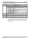
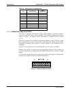
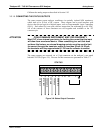
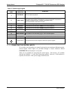
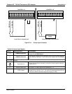
Table 3-6: Analog Output Pin Assignments
PIN ANALOG OUTPUT VOLTAGE SIGNAL CURRENT SIGNAL
1 V Out I Out +
2
A1
Ground I Out -
3 V Out I Out +
4
A2
Ground I Out -
5 V Out I Out +
6
A3
(Only used if an
optional O
2
or CO
2
sensor is installed)
Ground I Out -
7 V Out I Out +
8
A4
Ground I Out -
3.3.1.4. CURRENT LOOP ANALOG OUTPUTS (OPTION 41) SETUP
If your analyzer had this option installed at the factory, there are no further connections
to be made. The current loop option can be configured for any output range between 0
and 20 mA. Section 5.9.3.5 provides information on calibrating or adjusting these
outputs.
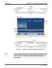
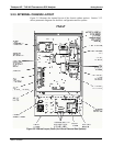
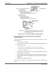
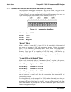
This section provides instructions for setting up the analog outp
uts for voltage and/or
current output. Figure 3-8 provides installation instructions and illustrates a sample
co
m
bination of one current output and two voltage outputs configuration.
For current output install the Current Loop option PCA on J19, on J21 or on J23 of
the motherboard.
For voltage output, install jumpers on J19, J21 and/or J23.
Following Figure 3-8 are instructions for converting current loop analog outputs to
standard 0-to-
5
VDC outputs.
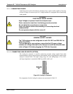
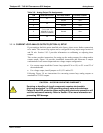
CAUTION – AVOID INVALIDATING WARRANTY
Servicing or handling of circuit components requires electrostatic
discharge protection, i.e. ESD grounding straps, mats and containers.
Failure to use ESD protection when working with electronic assemblies will
void the instrument warranty. Refer to Section 13 for more information on
preventing ESD damage.
06807C DCN6650