


Principles of Operation Teledyne API - T100 UV Fluorescence SO2 Analyzer
282
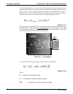
The Model 100 E UV Fluorescence SO
2
Analyzer is specifically designed to create these
circumstances.
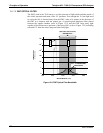
The light path is very short (x).
A reference detector measures the intensity of the available excitation UV light and
is used to remove effects of lamp drift (I
0
).
The temperature of the sample gas is measured and controlled via heaters attached to
the sample chamber so that the rate of decay (k) is constant.
A special hydrocarbon scrubber removes the most common interfering gases from
the sample gas.
And finally, the design of the sample chamber reduces the effects of stray light via
its optical geometry and spectral filtering.
The net result is that any variation in UV fluorescence can be directly attributed to
changes in the concentration of SO
2
in the sample gas.
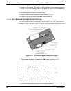
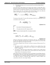
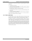
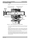
13.1.2. THE UV LIGHT PATH
The optical design of the T100’s sample chamber optimizes the fluorescent reaction
between SO
2
and UV Light (refer to Figure 13-2) and assure that only UV light resulting
from the decay of SO
2
* into SO
2
is sensed by the instruments fluorescence detector.
UV radiation is generated by a lamp specifically designed to produce a maximum
amount of light of the wavelength needed to excite SO
2
into SO
2
* (214 nm) and a
special reference detector circuit constantly measures lamp intensity (refer to (Equation
13-2)). A Photo Multi
plier Tube (PMT) detects the UV given off by the SO
2
* decay
(330 nm) and outputs an analog signal. Several focusing lenses and optical filters ensure
that both detectors are exposed to an optimum amount of only the right wavelengths of
UV. To further assure that the PMT only detects light given off by decaying SO
2
* the
pathway of the excitation UV and field of view of the PMT are perpendicular to each
other and the inside surfaces of the sample chamber are coated with a layer of black
Teflon
®
that absorbs stray light.
06807C DCN6650