


Calibration Procedures Teledyne API - T100 UV Fluorescence SO2 Analyzer
194
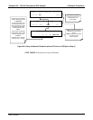
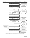
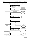
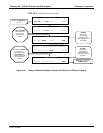
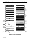
Step Three: Perform the calibration or calibration check according to the following
flow chart:
Wait until STABIL
falls below 0.05
ppb. This may
take several
minutes.
ZERO CAL M STABIL=XXX.X PPB SO2 =XXX.X
< TST TST > ZERO CONC
EXIT returns to the
main SAMPLE
display
Pressing ENTR changes the calibration of the instrument.
If either the ZERO or
SPAN button fails to
appear, see Chapter 11
for troubleshooting tips.
Analyzer enters ZERO
CAL mode.
EXIT returns the unit to
SAMPLE mode without
changing the calibration
values.
ZERO CAL M STABIL=XXX.X PPB SO2 =XXX.X
< TST TST > ZERO CONC EXIT
ZERO CAL M STABIL=XXX.X PPB SO2=X.XX X
< TST TST > CAL CALZ CALS SETUP
SPAN CAL M STABIL=XXX.X PPB SO2 =XXX.X
< TST TST > SPAN CONC EXIT
EXIT returns to the
SAMPLE mode without
changing the calibration
values.
A
CTION:
Allow zero gas to enter the sample port at the
rear of the instrument.
SAMPLE RANGE = 500.000 PPB SO2 =XXX.X
< TST TST > CAL CALZ CALS SETUP
SAMPLE STABIL=XXX.X PPB SO2 =XXX.X
< TST TST > CAL CALZ CALS SETUP
Scroll the display to the
STABIL test function. This
function calculates the stability
of the SO
2
measurements.
The value of STABIL
may jump
significantly. Wait
until it falls below 0.5
ppb. This may take
several minutes.
Pressing ENTR changes the calibration of the instrument.
Analyzer enters SPAN
CAL Mode.
SPAN CAL M STABIL=XXX.X PPB SO2 =XXX.X
< TST TST > ENTR CONC EXIT
SPAN CAL M STABIL=XXX.X PPB SO2 =XXX.X
< TST TST > SPAN CONC EXIT
ZERO CAL M STABIL=XXX.X PPB SO2 =XXX.X
< TST TST > ENTR CONC EXIT
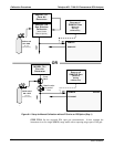
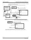
Figure 9-7: Setup for Manual Calibration with Z/S Valve Option Installed (Step 3)
06807C DCN6650