


Teledyne API - T100 UV Fluorescence SO2 Analyzer Getting Started
59
IMPORTANT
Leak Check:
Run a leak check once the appropriate pneumatic connections have
been made; check all pneumatic fittings for leaks using the
procedures defined in Section 11.3.6.
CAUTION – GENERAL SAFETY HAZARD
Gas flow though the analyzer must be maintained at all time for units with
a permeation tube installed. Insufficient gas flow allows gas to build up
to levels that will contaminate the instrument or present a safety hazard
to personnel.
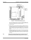
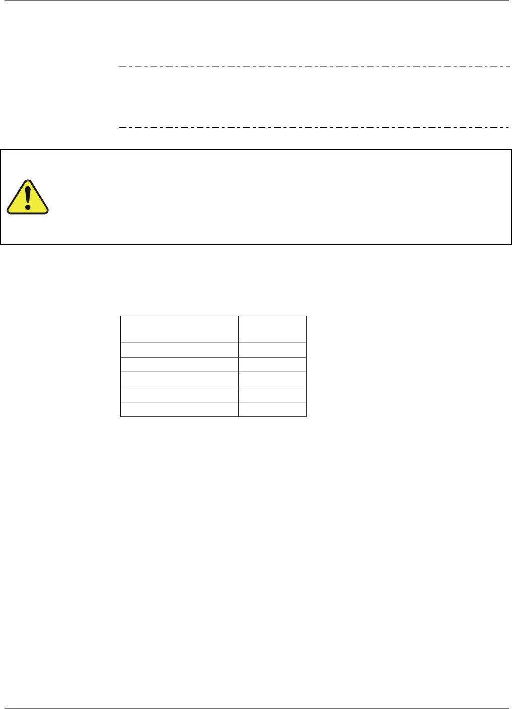
Section 3.3.2.1 provides external pneumatic connection instructions, and Table 3-9
provides links to the location of various internal pneumatic layout illustrations.
Table 3-9: Pneumatic Layout Reference
Pneumatic Layout Section
Basic 3.3.2.2
Zero/Span Valves 3.3.2.3
Internal Zero/Span (IZS) 3.3.2.4
Basic with O2 Sensor 3.3.2.8
Basic with CO2 Sensor 3.3.2.9
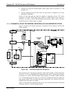
3.3.2.1. BASIC CONNECTIONS INCLUDING W/SPAN GAS AND W/GAS DILUTION CALIBRATOR
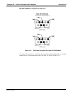
Refer to Figure 3-4 and Table 3-3 while making the pneumatic connections as follows:
SAMPLE inlet
Connect ¼” gas line not more than 2 m long, from sample gas
source to this inlet.
When no zero/span/shutoff valve options, also connect line from
calibration gas source to this inlet, but only when a calibration
operation is actually being performed.
EXHAUST outlet Connect exhaust line made of PTEF tubing; minimum O.D ¼”, to
this fitting. The exhaust line should be no longer than 10 meters,
and should lead outside the shelter or immediate area surrounding
the instrument.
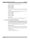
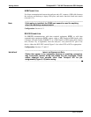
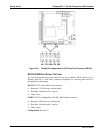
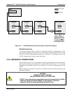
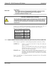
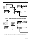
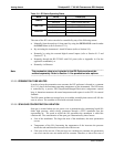
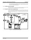
Figure 3-16 and Figure 3-17 illustrate pneumatic connections for two of the possible
basic configurations.
06807C DCN6650