


Teledyne API - T100 UV Fluorescence SO2 Analyzer Troubleshooting & Service
269
1. Set the analyzer display to show the signal I/O function, UVLAMP_SIGNAL (refer to
Section 12.1.3). UVLA
MP_SIGNAL is function 33.
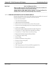
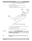
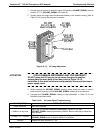
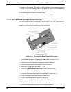
2. Slightly loosen the large brass thumbscrew located on the shutter housing (refer to
Figure 12-14) so that the lamp can be moved.
Figure 12-14. UV Lamp Adjustment
ATTENTION
COULD DAMAGE INSTRUMENT AND VOID WARRANTY
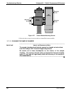
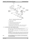
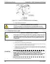
DO NOT grasp the UV lamp by its cap when changing its position -
always grasp the main body of the lamp (refer to Figure 12-13).
Inattention to this detail could t
w
ist and potentially disconnect the lamp’s
power supply wires.
3. While watching the UVLAMP_SIGNAL reading, slowly rotate the lamp or move it
back and forth vertically until the UVLAMP_SIGNAL reading is at its maximum.
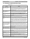
4. Compare the UVLAMP_SIGNAL reading to the information in Table 12-10 and
follow the instructions there.
Table 12
-10
: UV Lamp Signal Troubleshooting
UVLAMP_SIGNAL ACTION TO BE TAKEN
3500mV±200mV. No Action Required
> 4900mV at any time.
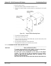
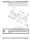
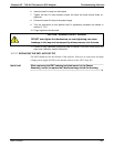
Adjust the UV reference detector potentiometer (Figure 12-15) until
UVLAMP_SIGNAL re
ads approximately 3600mV before continuing to adjust the
lamp position.
>3700mV or < 3300mV
Adjust the UV reference detector potentiometer (Figure 12-15) until
UVLAMP_SIGNAL reads
as close to 3500mV as possible.
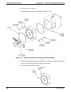
.< 600mV Replace the lamp (Section 12.7.2.6.
06807C DCN6650