


Getting Started Teledyne API - T100 UV Fluorescence SO2 Analyzer
46
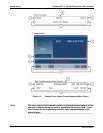
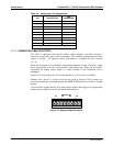
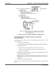
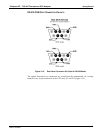
Figure 3-8: Current Loop Option Installed on the Motherboard
CONVERTING CURRENT LOOP ANALOG OUTPUTS TO STANDARD
VOLTAGE OUTPUTS
To convert an output configured for current loop operation to the standard 0 to 5 VDC
output operation:
1. Turn off power to the analyzer.
2. If a recording device was connected to the output being modified, disconnect it.
3. Remove the top cover
Remove the set screw located in the top, center of the rear panel
Remove the screws fastening the top cover to the unit (four per side).
Lift the cover straight up.
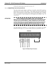
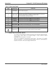
4. Disconnect the current loop option PCA from the appropriate connector on the
motherboard (refer to Figure 3-8).
5. Each co
nnector, J19 and J23, requires two shunts. Place one shunt on the
two left most pins and the second shunt on the two pins next to it (refer to
Figure 3-8).
6.
Reatta
ch the top case to the analyzer.
The analyzer is now ready to have a voltage-sensing, recording device attached to that
output.
06807C DCN6650