


Teledyne API - T100 UV Fluorescence SO2 Analyzer Troubleshooting & Service
259
VDC. The temperature set point (hard-wired into the preamplifier board) will vary by
about ±1 C due to component tolerances. The actual temperature will be maintained to
within 0.1 C around that set point.
On power-up of the analyzer, the front panel enables the user to watch that temperature
drop from about ambient temperature down to its set point of 6-8° C.
If the temperature fails to drop after 20 minutes, there is a problem in the cooler
circuit.
If the control circuit on the preamplifier board is faulty, a temperature of -1 C is
reported.
12.7. SERVICE PROCEDURES
This section contains some procedures that may need to be performed when a major
component of the analyzer requires repair or replacement.
ATTENTION
COULD DAMAGE INSTRUMENT AND VOID WARRANTY
Servicing of circuit components requires electrostatic discharge
protection, i.e. ESD grounding straps, mats and containers. Failure to
use ESD protection when working with electronic assemblies will void
the instrument warranty.
Refer to Section 13 for more information on preventing ESD damage.
12.7.1. DISK-ON-MODULE REPLACEMENT
Replacing the Disk-on-Module (DOM) will cause loss of all DAS data; it also may
cause loss of some instrument configuration parameters unless the replacement DOM
carries the exact same firmware version. Whenever changing the version of installed
software, the memory must be reset. Failure to ensure that memory is reset can cause the
analyzer to malfunction, and invalidate measurements. After the memory is reset, the
A/D converter must be re-calibrated, and all information collected in Step 1 below must
be re-entered before the instrument will function correctly. Also, zero and span
calibration should be performed.
1. Document all analyzer parameters that may have been changed, such as range,
auto-cal, analog output, serial port and other settings before replacing the DOM
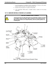
2. Turn off power to the instrument, fold down the rear panel by loosening the
mounting screws.
3. When looking at the electronic circuits from the back of the analyzer, locate the
Disk-on-Module in the right-most socket of the CPU board.
4. The DOM should carry a label with firmware revision, date and initials of the
programmer.
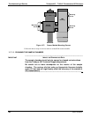
5. Remove the nylon fastener that mounts the DOM over the CPU board, and lift the
DOM off the CPU. Do not bend the connector pins.
6. Install the new Disk-on-Module, making sure the notch at the end of the chip
matches the notch in the socket.
06807C DCN6650