


Overview of Operating Modes Teledyne API - T100 UV Fluorescence SO2 Analyzer
82
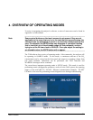
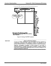
The Mode field of the front panel display indicates to the user which operating mode the
unit is currently running.
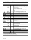
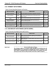
In addition to SAMPLE and SETUP, other modes available are presented in Table 4-1.
Table 4-1: Analyzer Operating Modes
MODE EXPLANATION
DIAG
One of the analyzer’s diagnostic modes is active (refer to Section 5.9).
LO CAL A
1
Unit is performing LOW SPAN (midpoint) calibration initiated automatically by the analyzer’s
AUTOCAL feature
LO CAL R
1
Unit is performing LOW SPAN (midpoint) calibration initiated remotely through the COM ports or
digital control inputs.
M-P CAL
1
This is the basic calibration mode of the instrument and is activated by pressing the CAL button.
SAMPLE
Sampling normally, flashing text indicates adaptive filter is on.
SAMPLE A
Indicates that unit is in SAMPLE mode and AUTOCAL feature is activated.
SETUP SETUP mode is being used to configure the analyzer. The gas measurement will continue during
this process.
SPAN CAL A
2
Unit is performing SPAN calibration initiated automatically by the analyzer’s AUTOCAL feature
SPAN CAL M
2
Unit is performing SPAN calibration initiated manually by the user.
SPAN CAL R
2
Unit is performing SPAN calibration initiated remotely through the COM ports or digital control
inputs.
ZERO CAL A
2
Unit is performing ZERO calibration procedure initiated automatically by the AUTOCAL feature
ZERO CAL M
2
Unit is performing ZERO calibration procedure initiated manually by the user.
ZERO CAL R
2
Unit is performing ZERO calibration procedure initiated remotely through the COM ports or digital
control inputs.
1
Other calibration procedures under CAL mode are described separately in Section 9.
2
Only Appears on units with Z/S valve or IZS options..
4.1. SAMPLE MODE
This is the analyzer’s standard operating mode. In this mode, the instrument is analyzing
SO
2
and calculating concentrations.
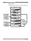
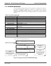
4.1.1. TEST FUNCTIONS
A series of test functions is available at the front panel while the analyzer is in
SAMPLE mode. These parameters provide information about the present operating
status of the instrument and are useful during troubleshooting (refer to Section 12.1.2).
They can als
o be recorded in one of the DAS channels (refer to Section 0) for data
analys
is. To view the test functions, press one of the <TST TST> buttons repeatedly in
either direction.
06807C DCN6650