


Troubleshooting & Service Teledyne API - T100 UV Fluorescence SO2 Analyzer
254
12.6.7.4. CONTROL INPUTS
The control input bits can be tested by the following procedure:
1. Connect a jumper from the +5 V pin on the STATUS connector to the U on the
CONTROL IN connector.
2. Connect a second jumper from the
pin on the STATUS connector to the A pin on
the CONTROL IN connector. The instrument should switch from SAMPLE mode to
ZERO CAL R mode.
3. Connect a second jumper from the
pin on the STATUS connector to the B pin on
the CONTROL IN connector. The instrument should switch from SAMPLE mode to
SPAN CAL R mode.
In each case, the T100 should return to SAMPLE mode when the jumper is removed.
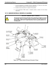
12.6.8. CPU
There are two major types of CPU board failures, a complete failure and a failure
associated with the Disk-On-Module (DOM). If either of these failures occurs, contact
the factory.
For complete failures, assuming that the power supplies are operating properly and the
wiring is intact, the CPU is faulty if on power-on, the watchdog LED on the
motherboard is not flashing.
In some rare circumstances, this failure may be caused by a bad IC on the motherboard,
specifically U57, the large, 44 pin device on the lower right hand side of the board. If
this is true, removing U57 from its socket will allow the instrument to start up but the
measurements will be invalid.
If the analyzer stops during initialization (the front panel display shows a fault or
warning message), it is likely that the DOM, the firmware or the configuration and data
files have been corrupted.
12.6.9. RS-232 COMMUNICATION
This section provides general RS-232 communication information.
12.6.9.1. GENERAL RS-232 TROUBLESHOOTING
Teledyne API’s analyzers use the RS-232 protocol as the standard, serial
communications protocol. RS-232 is a versatile standard, which has been used for many
years but, at times, is difficult to configure. Teledyne API conforms to the standard pin
assignments in the implementation of RS-232. Problems with RS-232 connections
usually center around 4 general areas:
Incorrect cabling and connectors. This is the most common problem. Refer to
Section 3.3.1.8 for connector, pin-out and setup information.
The comm
unications (baud) rate and protocol parameters are incorrectly configured.
Refer to 3.3.1.8 and 6.2 for baud rate information.
The COMM port commun
ications mode is set incorrectly (refer to Section 6.2.1).
If a
m
odem is used, additional configuration and wiring rules must be observed.
Refer to Section 8.3.
Incorrect setti
ng of the DTE - DCE Switch. Refer to Section 6.1.
06807C DCN6650