


Getting Started Teledyne API - T100 UV Fluorescence SO2 Analyzer
66
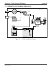
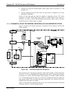
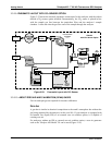
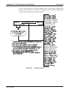
3.3.2.9. PNEUMATIC LAYOUT WITH CO
2
SENSOR OPTION
Figure 3-22 shows the internal, pneumatic connections for the analyzer with the carbon
dioxide (CO
2
) sensor option installed. Pneumatically, the CO
2
sensor is placed in line
with the sample gas line between the particulate filter and the analyzer’s sample
chamber. It does not alter the gas flow rate of the sample through the analyzer.
FLOW PRESSURE
SENSOR PCA
Chassis
with CO
2
Sensor Option
EXHAUST
GAS OUTLET
UV
LAMP
PMT
REACTION
CELL
PUMP
HYDROCARBON
SCRUBBER
(Kicker)
CO
2
Probe
SAMPLE
GAS INLET
SAMPLE
PRESSURE
SENSOR
FLOW
SENSOR
Figure 3-22: Pneumatic Layout with CO
2
Sensor
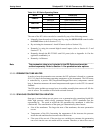
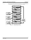
3.3.2.10. ABOUT ZERO AIR AND CALIBRATION (SPAN) GASES
Zero air and span gas are required for accurate calibration.
ZERO AIR
A gas that is similar in chemical composition to the earth’s atmosphere but without the
gas being measured by the analyzer, in this case SO
2
. If your analyzer is equipped with
an Internal Zero Span (IZS) or an external zero air scrubber option, it is capable of
creating zero air.
For analyzers without an IZS or external zero air scrubber option, a zero air generator
such as the Teledyne API Model 701 can be used (Figure 3-16).
06807C DCN6650