


Teledyne API - T100 UV Fluorescence SO2 Analyzer Principles of Operation
305
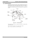
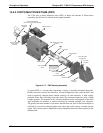
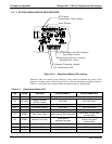
13.5.4.2. TEC CONTROL BOARD
The TEC control printed circuit assembly is located ion the sensor housing assembly,
under the slanted shroud, next to the cooling fins and directly above the cooling fan.
Using the amplified PMT temperature signal from the PMT preamplifier board (refer to
Section 13.5.5), it sets the drive voltage for the thermo
electric cooler. The warmer the
PMT gets, the more current is passed through the TEC causing it to pump more heat to
the heat sink.
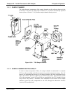
A red LED located on the top edge of this circuit board indicates that the control circuit
is receiving power. Four test points are also located at the top of this assembly. For the
definitions and acceptable signal levels of these test points refer to Section 12.1.2.
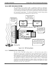
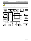
13.5.5. PMT PREAMPLIFIER
The PMT preamplifier board amplifies the PMT signal into a useable analog voltage that
can be processed by the motherboard into a digital signal to be used by the CPU to
calculate the SO
2
concentration of the gas in the sample chamber.
The output signal of the PMT is controlled by two different adjustments. First, the
voltage across the electron multiplier array of the PMT is adjusted with a set of two
hexadecimal switches. Adjusting this voltage directly affects the HVPS voltage and,
hence, the signal from the PMT. Secondly, the gain of the amplified signal can further
be adjusted through a potentiometer. These adjustments should only be performed when
encountering problems with the software calibration that cannot be rectified otherwise.
Refer to Section 12.7.2.8 for this hardware calibration.
06807C DCN6650