


Getting Started Teledyne API - T100 UV Fluorescence SO2 Analyzer
42
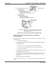
3.3. CONNECTIONS AND SETUP
This section presents the electrical (Section 3.3.1) and pneumatic (Section 3.3.2)
connections for setup and preparing for instrument operation.
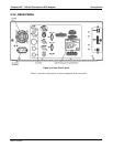
3.3.1. ELECTRICAL CONNECTIONS
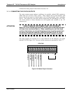
Note To maintain compliance with EMC standards, it is required that the cable
length be no greater than 3 meters for all I/O connections, which include
Analog In, Analog Out, Status Out, Control In, Ethernet/LAN, USB, RS-232,
and RS-485.
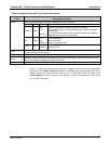
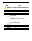
This section provides instructions for basic connections and for options. Table 3-4
provides a direct link to
the instructions for the subsections that apply to your analyzer’s
configuration.
Table 3-4: Electrical Connections References
Connection Section
Power 3.3.1.1
Analog Inputs (Option) 3.3.1.2
Analog Outputs 3.3.1.3
Current Loop Analog Outputs (Option),
and converting current to voltage output
3.3.1.4
Status Outputs 3.3.1.5
Control Inputs 3.3.1.6
Concentration Alarm Relay (Option) 3.3.1.7
Communications (Ethernet, USB,
RS-232, Multidrop, RS-485)*
3.3.1.8
* USB is an option with exceptions.
* RS-485 is an option and requires special setup (contact the Factory).
Either USB or RS-485 can be used; not both.
06807C DCN6650