


Teledyne API - T100 UV Fluorescence SO2 Analyzer Principles of Operation
303
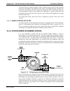
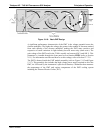
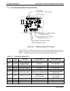
Figure 13-18: Basic PMT Design
A significant performance characteristic of the PMT is the voltage potential across the
electron multiplier. The higher the voltage, the greater is the number of electrons emitted
from each dynode of the electron multiplier, making the PMT more sensitive and
responsive to small variations in light intensity but also more noisy (dark noise). The
gain voltage of the PMT used in the T100 is usually set between 450 V and 800 V. This
parameter is viewable through the front panel as test function HVPS (refer to Section
4.1.1). For information on when and how to set this voltage, refer to Section 12.7.2.8.
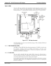
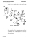
The PMT is housed inside the PMT m
odule assembly (refer to Figure 13-15 and Figure
13-17). This assembly
also includes the high voltage power supply required to drive the
PMT, an LED used by the instrument’s optical test function, a thermistor that measures
the temperature of the PMT and various components of the PMT cooling system
including the Thermo-Electric Cooler (TEC).
06807C DCN6650