


Principles of Operation Teledyne API - T100 UV Fluorescence SO2 Analyzer
306
COOLER (Closed Loop)
To
Motherboard
PMT Preamp PCA
E Test Control
From CPU
D-A
Converter
PMT
Coarse
Gain Set
(Rotary
PMT Fine
Gain Set
(Rotary
Switch)
PMT
Signal
Offset
E-Test
Generator
O-Test
Generator
O Test Control
From CPU
PMT Temp
Sensor
PMT
Temperature
Feedback
Circuit
TEC Control
PCA
PMT Out
p
ut
PMT HVPS
Drive Voltage
PMT Temp Analog Signal
to Motherboard
PMT Output Signal
(PMT) to Motherboard
O Test
LED
Amp to
Voltage
Converter/
Amplifier
Low Pass
Noise
Filter
MUX
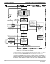
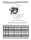
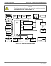
Figure 13-20: PMT Preamp Block Diagram
The PMT temperature control loop maintains the PMT temperature around 7° C and can
be viewed as test function PMT TEMP on the front panel (refer to Section 4.1.1).
The electrica
l test (ETEST) circuit generates a constant, electronic signal intended to
simulate the output of the PMT (after conversion from current to voltage). By bypassing
the detector’s actual signal, it is possible to test most of the signal handling and
06807C DCN6650