


Instrument Maintenance Teledyne API - T100 UV Fluorescence SO2 Analyzer
232
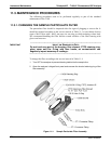
5. If there is a PMT response to the external light, symmetrically tighten the sample
chamber mounting screws or replace the 1/4” vacuum tubing with new, black PTFE
tubing (this tubing will fade with time and become transparent). Often, light leaks are
also caused by O-rings being left out of the assembly.
6. Carefully replace the analyzer cover.
7. If tubing was changed, carry out a leak check (refer to Section 11.3.6).
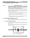
11.3.6. DETAILED PRESSURE LEAK CHECK
Obtain a leak checker similar to Teledyne API P/N 01960, which contains a small pump,
shut-off valve, and pressure gauge to create both over-pressure and vacuum.
Alternatively, a tank of pressurized gas, with the two stage regulator adjusted to ≤ 15
psi, a shutoff valve and pressure gauge may be used.
ATTENTION
COULD DAMAGE INSTRUMENT AND VOID WARRANTY
Once tube fittings have been wetted with soap solution under a
pressurized system, do not apply or re-apply vacuum as this will cause
soap solution to be sucked into the instrument, contaminating inside
surfaces.
Do not exceed 15 psi when pressurizing the system.
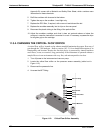
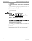
1. Turn OFF power to the instrument and remove the instrument cover.
2. Install a leak checker or a tank of gas (compressed, oil-free air or nitrogen) as
described above on the sample inlet at the rear panel.
3. Pressurize the instrument with the leak checker or tank gas, allowing enough time to
fully pressurize the instrument through the critical flow orifice.
4. Check each tube connection (fittings, hose clamps) with soap bubble solution,
looking for fine bubbles.
5. Once the fittings have been wetted with soap solution, do not re-apply vacuum as it
will draw soap solution into the instrument and contaminate it.
6. Do not exceed 15 psi pressure.
7. If the instrument has the zero and span valve option, the normally closed ports on
each valve should also be separately checked. Connect the leak checker to the
normally closed ports and check with soap bubble solution.
8. If the analyzer is equipped with an IZS Option, connect the leak checker to the Dry
Air inlet and check with soap bubble solution.
9. Once the leak has been located and repaired, the leak-down rate of the indicated
pressure should be less than 1 in-Hg-A (0.4 psi) in 5 minutes after the pressure is
turned off.
10. Clean soap solution from all surfaces, re-connect the sample and exhaust lines and
replace the instrument cover. Restart the analyzer.
06807C DCN6650