


Teledyne API - T100 UV Fluorescence SO2 Analyzer Troubleshooting & Service
261
IMPORTANT
IMPACT ON READINGS OR DATA
After any repair or service has been performed on the sensor module, the
T100 should be allowed to warm up for 60 minutes.
Always perform a leak check (refer to Section 11.3.6) and calibrate the
anal
y
zer (refer to Section 9) before placing it back in service.
12.7.2.1. REMOVING AND REINSTALLING THE SENSOR MODULE
Several of the procedures in this section either require the sensor module to be removed
from the instrument or are easier to perform if it has been removed.
To remove the Sensor Module:
1. Turn off the instrument power.
2. Open the top cover of the instrument:
Remove the set screw located in the top, center of the rear panel.
Remove the screws fastening the top cover to the unit (four per side).
Lift the cover straight up.
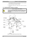
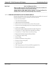
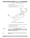
3. Disconnect the sensor module pneumatic lines (refer to Figure 12-6
Gas inlet line: 1/8” black Teflon line with stainless steel fitting.
Gas outlet line: 1/4” black Teflon
line with brass fitting.
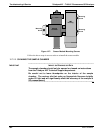
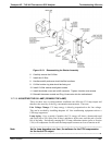
4. Disconnect all electrical wiring to the Sensor Module:
UV lamp power supply wiring
Shutter cabling
Reaction cell thermistor wiring (yellow)
Reaction cell heater wiring (red)
UV detector wiring
TEC power cable
PMT wiring (connectors J5 & J6 on the PMT preamplifier PCA)
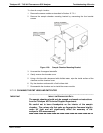
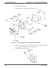
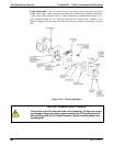
5. Remove the three sensor module mounting screws.
06807C DCN6650