


Teledyne API - T100 UV Fluorescence SO2 Analyzer Remote Operation of the Analyzer
177
Table 8-2: Control Input Pin Assignments
INPUT STATUS CONDITION WHEN ENABLED
A External Zero Cal
Zero calibration mode is activated. The mode field of the display will read
ZERO CAL R.
B External Span Cal
Span calibration mode is activated. The mode field of the display will read
SPAN CAL R.
C Unused
D Unused
E Unused
F Unused
Digital Ground Provided to ground an external device (e.g., recorder).
U
DC Power For Input
Pull Ups
Input for +5 VDC required to activate inputs A - F. This voltage can be taken
from an external source or from the “+” pin.
+ Internal +5v Supply
Internal source of +5V which can be used to activate inputs when connected
to pin U.
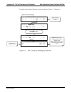
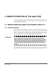
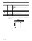
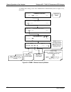
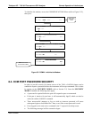
There are two methods to activate control inputs. The internal +5V available from the
“+” pin is the most convenient method (Figure 8-2). However, to ensure that these
inputs are trul
y isolated, a separate, external 5 VDC power supply should be used
(Figure 8-3).
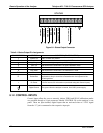
CONTROL IN
A B C D E F U
+
SPAN
ZERO
Figure 8-2: Control Inputs with Local 5 V Power Supply
06807C DCN6650