


Troubleshooting & Service Teledyne API - T100 UV Fluorescence SO2 Analyzer
274
21. Power up the analyzer and verify the basic operation of the analyzer using the
ETEST and OTEST features (refer to Section 6.9.5 and 6.9.6) or by measuring
calibrated zero and span gases.
22. Allow the instrument to warm up for 60 minutes.
23. Perform a PMT Hardware calibration (refer to Section 12.7.2.8).
24.
Perform a
zero point and span calibration (refer to Section 9).
12.7.2.8. PMT HARDWARE CALIBRATION (FACTORY CAL)
The sensor module hardware calibration adjusts the slope of the PMT output when the
instrument’s slope and offset values are outside of the acceptable range and all other
more obvious causes for this problem have been eliminated.
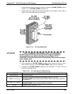
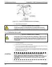
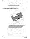
Figure 12-17: Pre-Amplifier Board (Preamp PCA) Layout
1. Set the instrument reporting range type to SNGL (refer to Section 5.4.3.1).
2. Perform a
zero–point calibration using zero air (refer to Section 9).
3. Let the instru
ment stabilize by allowing it to run for one hour.
4. Adjust the UV Lamp (refer to Section 12.7.2.5).
5. Perform a L
AMP CALIBRATION procedure (refer to Section 5.9.6).
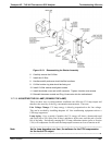
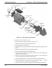
6. Locate the Preamp PCA (refer to Figu
re 12-16).
7. Locate the Fo
llowing Components On the Preamp PCA (Figure 12-17):
8. HVPS coarse adjustment switch (Range
0-9, then A-F).
9. HVPS fine adjustment switch (Range 0-9, then A-F).
10. Gain adjustment potentiometer (Full scale is 10 to 12 turns).
11. Set the HVPS coarse adjustment to its minimum setting (0).
12. Set the HVPS fine adjustment switch to its maximum setting (F).
06807C DCN6650