Teledyne API - T100 UV Fluorescence SO2 Analyzer
xviii
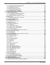
Figure 9-9: Setup for Manual Calibration Check with Z/S Valve or IZS Option (Step 1) ............................ 196
Figure 9-10: Setup for Manual Calibration Check with Z/S Valve or IZS Option (Step 2) ............................ 197
Figure 9-11: Manual Calibration in Dual/Auto Reporting Range Modes....................................................... 198
Figure 9-12: AUTO CAL – User Defined Sequence...................................................................................... 201
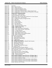
Figure 9-13: O
2
Sensor Calibration Set Up ................................................................................................... 203
Figure 9-14: O
2
Span Gas Concentration Set Up ......................................................................................... 204
Figure 9-15: Activate O
2
Sensor Stability Function ....................................................................................... 205
Figure 9-16: O
2
Zero/Span Calibration.......................................................................................................... 206
Figure 9-17: CO
2
Sensor Calibration Set Up................................................................................................. 207
Figure 9-18: CO
2
Span Gas Concentration Setup ........................................................................................ 208
Figure 9-19: Activate CO
2
Sensor Stability Function .................................................................................... 209
Figure 9-20: CO
2
Zero/Span Calibration ....................................................................................................... 210
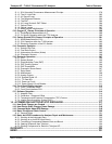
Figure 10-1: Dynamic Multipoint Span Calibration........................................................................................ 219
Figure 11-1: Sample Particulate Filter Assembly.......................................................................................... 228
Figure 11-2: Critical Flow Orifice Assembly .................................................................................................. 230
Figure 11-3: Simple Leak Check Fixture....................................................................................................... 233
Figure 11-4: Hydrocarbon Scrubber Leak Check Setup ............................................................................... 234
Figure 12-1: Viewing and Clearing Warning Messages................................................................................ 237
Figure 12-2: Example of Signal I/O Function ................................................................................................ 242
Figure 12-3: CPU Status Indicator ................................................................................................................ 243
Figure 12-4: Location of Relay Board Power Configuration Jumper............................................................. 250
Figure 12-5: Manual Activation of the UV Light Shutter................................................................................ 256
Figure 12-6: Sensor Module Wiring and Pneumatic Fittings......................................................................... 260
Figure 12-7: Sensor Module Mounting Screws............................................................................................. 262
Figure 12-8: Sample Chamber Mounting Bracket......................................................................................... 263
Figure 12-9: Hex Screw Between Lens Housing and Sample Chamber ...................................................... 264
Figure 12-10: UV Lens Housing / Filter Housing............................................................................................. 265
Figure 12-11: PMT UV Filter Housing Disassembled ..................................................................................... 265
Figure 12-12: Disassembling the Shutter Assembly ....................................................................................... 267
Figure 12-13: Shutter Assembly...................................................................................................................... 268
Figure 12-14. UV Lamp Adjustment................................................................................................................ 269
Figure 12-15: Location of UV Reference Detector Potentiometer .................................................................. 270
Figure 12-16: PMT Assembly - Exploded View............................................................................................... 272
Figure 12-17: Pre-Amplifier Board (Preamp PCA) Layout .............................................................................. 274
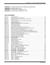
Figure 13-1: UV Absorption........................................................................................................................... 280
Figure 13-2: UV Light Path............................................................................................................................ 283
Figure 13-3: Source UV Lamp Construction ................................................................................................. 284
Figure 13-4: Excitation Lamp UV Spectrum Before/After Filtration............................................................... 285
Figure 13-5: PMT Optical Filter Bandwidth ................................................................................................... 286
Figure 13-6: Effects of Focusing Source UV in Sample Chamber................................................................ 287
Figure 13-7: Oxygen Sensor - Principles of Operation ................................................................................. 290
Figure 13-8: CO
2
Sensor Principles of Operation ......................................................................................... 291
Figure 13-9: CO2 Sensor Option PCA Layout and Electronic Connections................................................. 292
Figure 13-10: Gas Flow and Location of Critical Flow Orifice......................................................................... 293
Figure 13-11: Flow Control Assembly & Critical Flow Orifice.......................................................................... 294
Figure 13-12: T100 Hydrocarbon Scrubber (Kicker)....................................................................................... 295
Figure 13-13: T100 Electronic Block Diagram ................................................................................................ 297
Figure 13-14: CPU Board Annotated .............................................................................................................. 299
Figure 13-15: T100 Sensor Module................................................................................................................. 300
Figure 13-16: T100 Sample Chamber............................................................................................................. 301
Figure 13-17: PMT Housing Assembly............................................................................................................ 302
Figure 13-18: Basic PMT Design .................................................................................................................... 303
Figure 13-19: PMT Cooling System ................................................................................................................ 304
Figure 13-20: PMT Preamp Block Diagram .................................................................................................... 306
Figure 13-21: Relay Board Status LED Locations .......................................................................................... 308
Figure 13-22: Power Distribution Block Diagram ............................................................................................ 312
Figure 13-23: Front Panel and Display Interface Block Diagram.................................................................... 313
Figure 13-24: Basic Software Operation ......................................................................................................... 314
06807C DCN6650


