


Teledyne API - T100 UV Fluorescence SO2 Analyzer Principles of Operation
311
In its standard configuration, the analyzer comes with all four of these channels set up to
output a DC voltage. However, 4-20mA current loop drivers can be purchased for the
first two of these outputs (A1 and A2). Refer to Sections 1.4 (Option 41), 3.3.1.3 and
5.9.3.5.
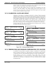
Output Loop-back: All three of the functioning an
alog outputs are connected back to
the A/D converter through a Loop-back circuit. This permits the voltage outputs to be
calibrated by the CPU without need for any additional tools or fixtures (refer to Section
5.9.3.2).
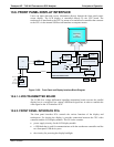
13.5.10. EXTERNAL DIGITAL I/O
This External Digital I/O performs two functions.
STATUS OUTPUTS: Logic-Level voltages are output through an optically isolated 8-
pin connector located on the rear panel of the analyzer. These outputs convey good/bad
and on/off information about certain analyzer conditions. They can be used to interface
with certain types of programmable devices (refer to Section 8.1.1).
CO
NTROL INPUTS: By applying +5VDC power supplied from an external source
such as a PLC or Data logger (refer to Section 8.1.2), Zero and Span calibrations can be
initiated by c
ontact closures on the rear panel.
13.5.11. I
2
C DATA BUS
I
2
C is a two-wire, clocked, bi-directional, digital serial I/O bus that is used widely in
commercial and consumer electronic systems. A transceiver on the Motherboard
converts data and control signals from the PC-104 bus to I
2
C. The data is then fed to the
relay board and optional analog input circuitry.
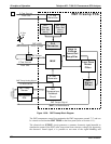
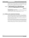
13.5.12. POWER UP CIRCUIT
This circuit monitors the +5V power supply during start-up and sets the Analog outputs,
External Digital I/O ports, and I
2
C circuitry to specific values until the CPU boots and
the instrument software can establish control.
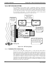
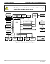
13.5.13. POWER SUPPLY/ CIRCUIT BREAKER
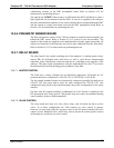
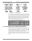
The analyzer operates on 100 VAC, 115 VAC or 230 VAC power at either 50Hz or
60Hz. Individual units are set up at the factory to accept any combination of these five
attributes. As illustrated in Figure 13-22 below, power enters the analyzer through a
standard IEC 320 power receptacle located on the rear panel of
the instrument. From
there it is routed through the ON/OFF switch located in the lower right corner of the
front panel.
AC line power is stepped down and converted to DC power by two DC power supplies.
One supplies +12 VDC, for various valves and valve options, while a second supply
provides +5 VDC and ±15 VDC for logic and analog circuitry as well as the TEC
cooler. All AC and DC Voltages are distributed through the relay board.
A 6.75 ampere circuit breaker is built into the ON/OFF switch. In case of a wiring fault
or incorrect supply power, the circuit breaker will automatically turn off the analyzer.
06807C DCN6650