


Teledyne API - T100 UV Fluorescence SO2 Analyzer Principles of Operation
307
conditioning circuitry on the PMT preamplifier board. Refer to Section 5.9.5 for
instructions on performing this test.
The optical test (OTEST) feature causes an LED inside the PMT cold block to create a
light signal that can be measured with the PMT. If zero air is supplied to the analyzer,
the entire measurement capability of the sensor module can be tested including the PMT
and the current to voltage conversion circuit on the PMT preamplifier board. Refer to
Section 5.9.4 for instructions on performing this test.
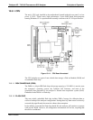
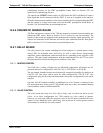
13.5.6. PNEUMATIC SENSOR BOARD
The flow and pressure sensors of the T100 are located on a printed circuit assembly just
behind the PMT sensor. Refer to Section 12.6.15 on how to test this assembly. The
signals of this board are supplied to the m
otherboard for further signal processing. All
sensors are linearized in the firmware and can be span calibrated from the front panel.
Refer to Section 5.4.3.2 for instructions on performing this test.
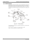
13.5.7. RELAY BOARD
The relay board is the central switching unit of the analyzer. It contains power relays,
status LEDs for all heated zones and valves, as well as valve drivers, thermocouple
amplifiers, power distribution connectors and the two switching power supplies of the
analyzer. The relay board communicates with the motherboard over the I
2
C bus and is
the main board for trouble-shooting power problems of any kind.
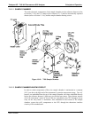
13.5.7.1. HEATER CONTROL
The T100 uses a variety of heaters for its individual components. All heaters are AC
powered and can be configured for 100/120 VAC or 220/230VAC at 50-60 Hz.
The two sample chamber heaters are electronically connected in parallel for analyzers at
100/120 VAC line power and in series for units configured for 220/230 VAC. One
configuration plug on the relay board determines the power configuration for the entire
analyzer.
On units with IZS options installed, an additional set of AC heaters is attached to the
IZS permeation tube. Some special T100 models may have other, non-standard heating
zones installed, such as a dilution manifold.
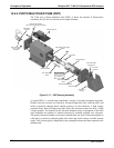
13.5.7.2. VALVE CONTROL
The relay board also hosts two valve driver chips, each of which can drive up four
valves. In its basic configuration the T100 requires no valve control to operate.
However, on units with either the zero/span valve or the IZS option installed, the valve
control is used. Manifold valves, which may also be present in certain special versions
of the analyzer, would also use valve control.
06807C DCN6650