


Teledyne API - T100 UV Fluorescence SO2 Analyzer SETUP Menu
125
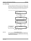
5.9.4. OPTIC TEST
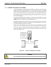
The optic test function tests the response of the PMT sensor by turning on an LED
located in the cooling block of the PMT (refer to Figure 13-18). The analyzer uses the
light emitted
from the LED to test its photo-electronic subsystem, including the PMT
and the current to voltage converter on the pre-amplifier board. To ensure that the
analyzer measures only the light coming from the LED, the analyzer should be supplied
with zero air. The optic test should produce a PMT signal of about 2000±1000 mV.
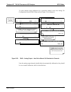
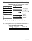
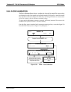
Access the Optic Test from the DIAG Menu (refer to Figure 5-16), then press:
DIAG SIGNAL I / O
PREV NEXT JUMP ENTR EXIT
DIAG OPTIC RANGE = 500.000 PPB SO2=XXX.X
<TST TST> EXIT
Press NEXT until…
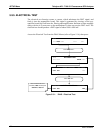
DIAG OPTIC TEST
PREV NEXT ENTR EXIT
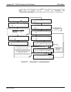
Press TST until…
DIAG ELEC PMT = 2751 MV
SO2=XXX.X
<TST TST> EXIT
While the optic test is
activated, PMT should be
2000 mV ± 1000 mV
Figure 5-30: DIAG – Optic Test
IMPORTANT
IMPACT ON READINGS OR DATA
This is a coarse test for functionality and not an accurate calibration tool.
The resulting PMT signal can vary significantly over time and also
changes with low-level calibration.
06807C DCN6650