


Teledyne API - T100 UV Fluorescence SO2 Analyzer Troubleshooting & Service
257
the supply. The second is the programming voltage which is generated on the Preamp
Board. This power supply is unlike a traditional PMT HVPS. It is like having 10
independent power supplies, one to each pin of the PMT. The test procedure below
allows you to test each supply.
1. Check the HVPS test function via the front panel and record the reading level.
Adjustment of the HVPS output level is covered in the hardware calibration
procedure in Section 12.7.2.8.
2.
Turn off the instru
ment.
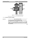
3. Remove the cover and disconnect the 2 connectors at the front of the PMT housing.
4. Remove the end plate from the PMT housing.
5. Remove the HVPS/PMT assembly from the cold block inside the sensor. Un-plug
the PMT.
6. Re-connect the 7 pin connector to the Sensor end cap, and power-up the
instrument.
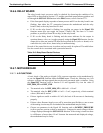
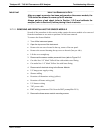
7. Check the voltages between the pairs of pins listed in Table 12-9. The result for
each pair
sh
ould be equal and approximately 10% of the reading level recorded in
Step 1.
Table 12-9: Example of HVPS Power Supply Outputs
If HVPS reading = 700 VDC
PIN PAIR NOMINAL READING
1 2 70 VDC
2 3 70 VDC
3 4 70 VDC
4 5 70 VDC
5 6 70 VDC
6 7 70 VDC
7 8 70 VDC
KEY
5
6
7
8
9
10
11
1
2
3
4
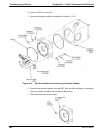
8. Turn off the instrument power, and re-connect the PMT tube, and then re-assemble
the sensor.
If any faults are found in the test, the HVPS must be replaced. There are no user
serviceable parts inside the HVPS.
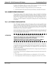
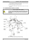
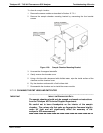
12.6.15. PNEUMATIC SENSOR ASSEMBLY
The pressure/flow sensor circuit board, located behind the sensor assembly, can be
checked with a voltmeter using the following procedure, which assumes that the wiring
is intact and that the motherboard and the power supplies are operating properly.
Measure the voltage across TP1 and TP2, it should be 10.0 0.25 V. If not, the
board may be faulty.
Measure the voltage across capacitor C2; it should be 5.0 ± 0.25 V. If not, the board
may be faulty.
06807C DCN6650