


Troubleshooting & Service Teledyne API - T100 UV Fluorescence SO2 Analyzer
258
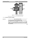
12.6.16. SAMPLE PRESSURE
Measure the voltage across test points TP1 and TP4. With the sample pump
disconnected or turned off, this voltage should be 4500 250 mV. With the pump
running, it should be about 0.2 V less as the sample pressure drops by about 1 in-Hg-A
from ambient pressure. If this voltage is significantly different, the pressure transducer
S2 or the board may be faulty. A leak in the sample system to vacuum may also cause
this voltage to be between about 0.6 and 4.5. Ensure that the front panel reading of the
sample pressure is at about 1 in-Hg-A less than ambient pressure.
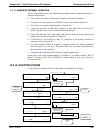
12.6.17. IZS OPTION
The zero/span valves and IZS options need to be enabled in the software (contact the
factory on how to do this). Refer to Figure 3-19 and Figure 3-20 for a flow diagram with
zero/span valve or IZS opti
on.
Check for the physical presence of the valves or the IZS option.
Check that a working perm-tube is installed in the IZS oven assembly.
Check front panel for correct software configuration. When the instrument is in
SAMPLE mode, the front panel display should show CALS and CALZ buttons in
the second line of the display. The presence of the buttons indicates that the option
has been enabled in software. In addition, the IZS option is enabled if the TEST
functions show a parameter named IZS TEMP.
The IZS option is heated with a proportional heater circuit and the temperature is
maintained at 50° C ±1°. Check the IZS TEMP function via front panel display (refer to
Section 4.1.1) and the IZ
S_TEMP signal voltage
using the SIGNAL I/O function
under the DIAG Menu (refer to Section 5.9.1).
At 50°
C, the temperature signal from the IZS thermistor should be around 2500 mV.
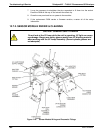
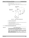
12.6.18. BOX TEMPERATURE
The box temperature sensor (thermistor) is mounted on the motherboard at the bottom,
right corner of the CPU board when looking at it from the front. It cannot be
disconnected to check its resistance. Box temperature will vary with, but will always
read about 5° C higher than, ambient (room) temperature because of the internal heating
zones sample chamber and other devices.
To check the box temperature functionality, we recommend checking the BOX_TEMP
signal voltage using the SIGNAL I/O function under the DIAG Menu (refer to Section
5.9.1).
At about 30°
C (5 above typical room temperature), the signal should be around 1500
mV. We recommend using a certified or calibrated external thermometer / temperature
sensor to verify the accuracy of the box temperature.
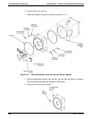
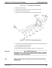
12.6.19. PMT TEMPERATURE
PMT temperature should be low and constant. It is more important that this temperature
is maintained constant than it is to maintain it low. The PMT cooler uses a Peltier,
thermo-electric element powered by 12 VDC from the switching power supply PS2. The
temperature is controlled by a proportional temperature controller located on the
preamplifier board. Voltages applied to the cooler element vary from +/- 0.1 to +/- 12
06807C DCN6650