


Principles of Operation Teledyne API - T100 UV Fluorescence SO2 Analyzer
308
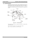
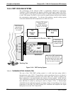
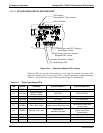
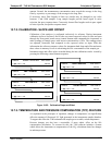
13.5.7.3. STATUS LEDS & WATCH DOG CIRCUITRY
Zero/Span and IZS Options
Sample/CAL Valve
IZS Option
Permeation Tube Heater
Dark Shutter
Sample Chamber Heater
I2C Watchdog LED
Zero/Span and IZS Options
Zero/Span Valve
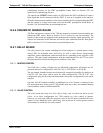
Figure 13-21: Relay Board Status LED Locations
Thirteen LEDs are located on the analyzer’s relay board to indicate the status of the
analyzer’s heating zones and valves as well as a general operating watchdog indicator.
Table 13-1 shows the state of these LEDs and their respective functionality.
Table 13-1: Relay Board Status LED’s
LED COLOR FUNCTION STATUS WHEN LIT STATUS WHEN UNLIT
D1 RED Watchdog circuit
Cycles On/Off every 3 seconds under control of the CPU.
D2 YELLOW
Sample chamber
(RCELL) heater
HEATING NOT HEATING
D3, D4 YELLOW Unused N/A N/A
D5 YELLOW IZS heater (option) HEATING NOT HEATING
D6 YELLOW Unused N/A N/A
D7 GREEN Zero / Span Valve Valve open to Span Gas path
Valve open to Zero Gas
(normal state)
D8 GREEN Sample / Cal Valve
Valve open to
calibration gas path
Valve open to sample gas
inlet on rear panel
(normal state)
D9, D10 GREEN Unused N/A N/A
D11 GREEN UV Lamp Shutter Shutter open Shutter closed
D12-14 GREEN Unused N/A N/A
06807C DCN6650