


Teledyne API - T100 UV Fluorescence SO2 Analyzer Troubleshooting & Service
251
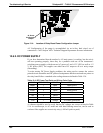
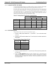
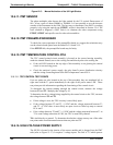
Table 12-5: DC Power Supply Acceptable Levels
CHECK RELAY BOARD TEST POINTS
FROM TEST POINT TO TEST POINT
POWER
SUPPLY
VOLTAGE
NAME # NAME #
MIN V MAX V
PS1 +5 DGND 1 +5 2 +4.80 +5.25
PS1 +15 AGND 3 +15 4 +13.5 +16.0
PS1 -15 AGND 3 -15V 5 -14.0 -16.0
PS1 AGND AGND 3 DGND 1 -0.05 +0.05
PS1 Chassis DGND 1 Chassis N/A -0.05 +0.05
PS2 +12 +12V Ret 6 +12V 7 +11.8 +12.5
PS2 DGND +12V Ret 6 DGND 1 -0.05 +0.05
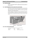
12.6.3. I
2
C BUS
Operation of the I
2
C bus can be verified by observing the behavior of D1 on the relay
PCA & D2 on the Valve Driver PCA . Assuming that the DC power supplies are
operating properly, the I
2
C bus is operating properly if: D1 on the relay PCA and D2 of
the Valve Driver PCA are flashing
There is a problem with the I
2
C bus if both D1 on the relay PCA and D2 of the Valve
Driver PCA are ON/OFF constantly.
12.6.4. TOUCH-SCREEN INTERFACE
Verify the functioning of the touch screen by observing the display when pressing a
touch-screen control button. Assuming that there are no wiring problems and that the
DC power supplies are operating properly, but pressing a control button on the touch
screen does not change the display, any of the following may be the problem:
The touch-screen controller may be malfunctioning.
The internal USB bus may be malfunctioning.
You can verify this failure by logging on to the instrument using APICOM or a terminal
program. If the analyzer responds to remote commands and the display changes
accordingly, the touch-screen interface may be faulty.
12.6.5. LCD DISPLAY MODULE
Verify the functioning of the front panel display by observing it when power is applied
to the instrument. Assuming that there are no wiring problems and that the DC power
supplies are operating properly, the display screen should light and show the splash
screen and other indications of its state as the CPU goes through its initialization
process.
06807C DCN6650