


Teledyne API - T100 UV Fluorescence SO2 Analyzer Troubleshooting & Service
253
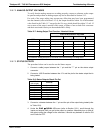
12.6.7.2. ANALOG OUTPUT VOLTAGES
To verify that the analog outputs are working properly, connect a voltmeter to the output
in question and perform an analog output step test as described in Section 5.9.2.
For each of th
e steps, taking into account any offset that may have been programmed
into the channel (refer to Section 5.9.3.4), the output should be within 1% of the nominal
value listed in the Table 11
-7 except for the 0% step, which should be within 2-3 mV. If
one or more of the steps is outside of this range, a failure of one or both D/A converters
and their associated circuitry on the motherboard is likely.
Table 12-7: Analog Output Test Function - Nominal Values
FULL SCALE OUTPUT VOLTAGE
100MV 1V 5V
10V*
STEP % NOMINAL OUTPUT VOLTAGE
1 0 0 mV 0 0 0
2 20 20 mV 0.2 1 2
3 40 40 mV 0.4 2 4
4 60 60 mV 0.6 3 6
5 80 80 mV 0.8 4 8
6 100 100 mV 1.0 5 10
* Increase the Analog Out (AOUT) Cal Limits in the DIAG>Analog I/O Config menu.
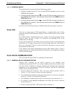
12.6.7.3. STATUS OUTPUTS
The procedure below can be used to test the Status outputs.
1. Connect a cable jumper between the “-“ pin and the “” pin on the status output
connector.
2. Connect a 1000 Ω resistor between the +5 V and the pin for the status output that is
being tested.
Table 12-8: Status Outputs Check Pin Out
PIN
(left to right)
STATUS
1 System Ok
2 Conc Valid
3 High Range
4 Zero Cal
5 Span Cal
6 Diag Mode
7 Spare
8 Spare
3. Connect a voltmeter between the “-“ pin and the pin of the output being tested (refer
to Table 12-8).
4. Under
the DIAG SIGNAL I/O menu (refer to Section 5.9.1), scroll through the
inputs and o
utputs until you get to the output in question. Alternately turn on and off
the output noting the voltage on the voltmeter, it should vary between 0 volts for ON
and 5 volts for OFF.
06807C DCN6650