


DEFINITY Enterprise Communications Server Release 6
Installation and Test for Multi-Carrier Cabinets
555-230-112
Issue 5
May 1998
Install Telecommunications Cabling
Page 2-47Patch Cord/Jumper Installation and Administration
2
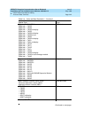
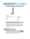
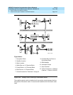
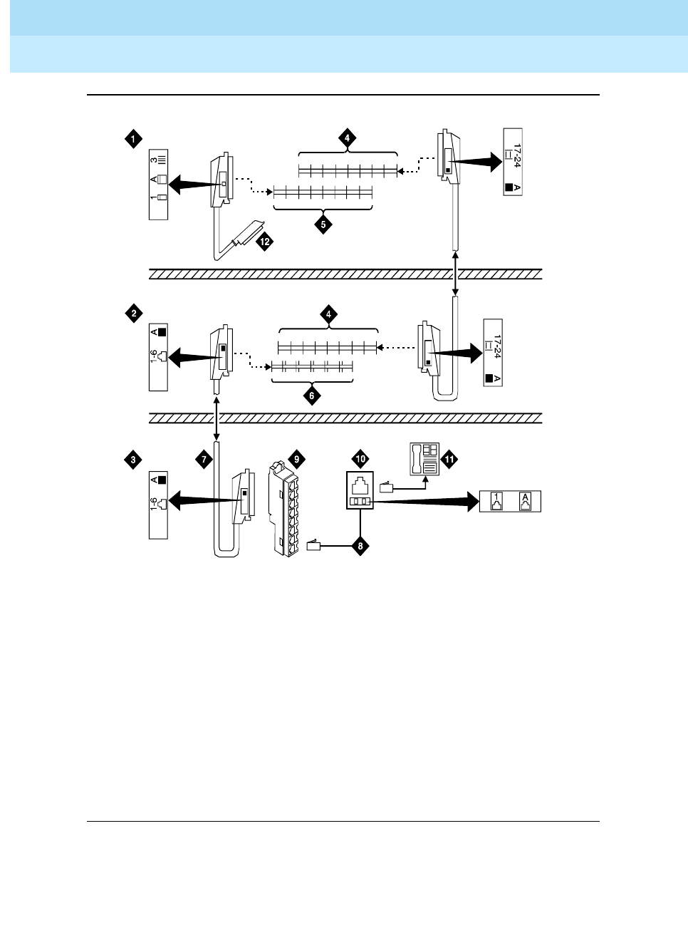
Figure 2-26. Example 3-Pair Labeling to Information Outlet
The satellite symbol must be installed at all connection points between the blue
field and the information outlet. It must also be installed at the information outlet
itself.
Figure Notes:
1. Equipment Room
2. Satellite Location
3. Work Location
4. White Row on 110 Terminal Block
5. Purple Row on 110 Terminal Block
6. Blue Row on 110 Terminal Block
7. Central Location for Terminals 1 through 6
8. D-Inside Wire Cut Down to
Connecting Block
9. 258A Adapter
10. Information Outlet
11. Voice Terminal
12. To Port Connector on Cabinet
(Cabinet 1, Carrier A, Slot 03)
crdf5prCJL103096