


DEFINITY Enterprise Communications Server Release 6
Installation and Test for Multi-Carrier Cabinets
555-230-112
Issue 5
May 1998
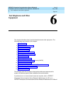
Install and Wire Telephones and Other Equipment
Page 5-150Connector and Cable Diagrams (Pinout Charts)
5
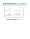
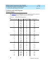
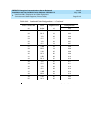
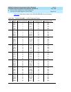
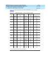
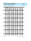
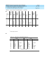
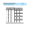
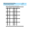
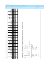
Table 5-31. TN1654 Lead Designations
* Denotes an active low signal.
Pin Color Designation Pin Color Designation
26 W-BL +5E 01 BL-W +5E
27 W-O GRD 02 O-W XMITDAT -
28 W-G GRD 03 G-W GRD
29 W-BR XMITDAT + 04 BR-W RCVDAT -
30 W-SL GRD 05 SL-W GRD
31 R-BL RCVDAT + 06 BL-R GRD
32 R-O +5E 07 O-R +5E
33 R-G CCSYNC 08 G-R CDSYNC
34 R-BR C2DCDATA 09 BR-R C2DDDATA
35 R-SL CASYNC 10 SL-R CBSYNC
36 BK-BL D2CDATA 11 BL-BK ISCLOCK
37 BK-O CCPRES 12 O-BK CDPRES
38 BK-G LID * 13 G-BK LID
39 BK-BR LOD 14 BR-BK LOD*
40 BK-SL CCRESET 15 SL-BK CDRESET
41 Y-BL LIC* 16 BL-Y LIC
42 Y-O LOC 17 O-Y LOC*
43 Y-G CARESET 18 G-Y CBRESET
44 Y-BR LIB* 19 BR-Y LIB
45 Y-SL LOB 20 SL-Y LOB*
46 V-BL C2DADATA 21 BL-V C2DBDATA
47 V-O LIA* 22 O-V LIA
48 V-G LOA 23 G-V LOA*
49 V-BR CAPRES 24 BR-V CBPRES
50 V-SL GRD 25 SL-V GRD