


DEFINITY Enterprise Communications Server Release 6
Installation and Test for Multi-Carrier Cabinets
555-230-112
Issue 5
May 1998
Install Telecommunications Cabling
Page 2-20Cable Installation
2
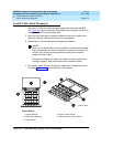
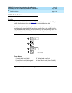
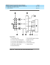
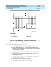
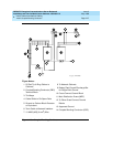
■ Route the cable from the cabinet to the wall. Place the cable beside 1 of
the rows of columns in the cable slack manager.
NOTE:
Retainers mounted on the columns keep the cable from protruding
above the top of the base of the cable slack manager.
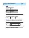
■ Determine the length of the cable required to reach from the cable slack
manager to the assigned connecting/terminal block.
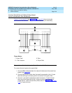
■ The cable must be supported on the wall using “D” rings.
■ Cable slack is stored by coiling the cable around the columns in the cable
slack manager. The first run should always go across the full length of the
5 columns in the cable slack manager.
■ Connect the cable to the assigned connecting/terminal block.
■ Avoid placing copper cables where they may bend or strain fiber optic
cables.
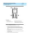
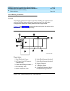
Install Control Carrier Outputs Cable
A connector on the rear of the Control Carrier is labeled AUX. A 25-pair cable
connects the AUX connector to a 110-type terminal block in the yellow field of
the trunk/auxiliary field. The AUX connector outputs include the following:
■ Alarm monitoring for the processor interface
■ 7 DC power (-48 VDC) sources for emergency transfer units
■ 3 DC power (-48 VDC) sources for remotely powering a total of 3 attendant
consoles or executive voice terminal adjuncts
■ The remote maintenance internal modem connection location
■ Access to a relay contact is available to actuate a light, bell, or similar type
customer-supplied device. The relay can be administered to make contact
when a major, minor, or warning alarm condition occurs in the system
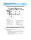
Label Control Carrier Cable
Place the appropriate AUX connector label on the assigned 110-type terminal
block row. On the control carrier cable, place a yellow auxiliary label on the
connectors at each end of the cable. Write “AUX” on each label.