


DEFINITY Enterprise Communications Server Release 6
Installation and Test for Multi-Carrier Cabinets
555-230-112
Issue 5
May 1998
Install Telecommunications Cabling
Page 2-13Install Sneak Fuse Panels
2
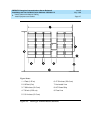
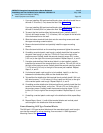
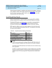
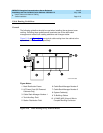
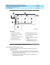
Cable clamps are required in installations with cable slack managers. At the rear
of the cabinets, install 2 cable clamps using the screws provided. These clamps
hold the 25-pair input/output or MDF cables in place. Figure 2-6
shows cable
clamp placement and cable routing.
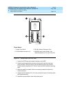
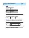
Install Sneak Fuse Panels
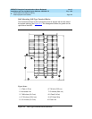
Sneak current protection is required between the incoming RJ21X or RJ2GX
network interface and the system for both trunk and off-premise circuit packs.
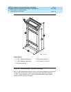
The Model 507B sneak current fuse panel, or equivalent, is recommended for
sneak current protection. See Figure 2-7
. The panel contains two 25-pair
connectors, fuse removal tool, and fifty 220029 Sneak Fuses (and 2 spares).
B25A connector cables connect the network interface to the sneak fuse panel.
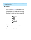
Also, 157B connecting blocks equipped with SCP-110 protectors can be used
for sneak current protection.
NOTE:
Sneak current protectors with a rating of 350 mA at 600 Volts must be UL
listed for domestic installation and CSA certified for Canadian installation.
The 507B includes 52 sneak fuses and 2 cables and can be ordered using
PEC code 63210.
The SCP-110 protectors are used with 110-type hardware and on the 507B
Sneak Fuse Panel. The SCP-110 Protectors can be ordered separately and
installed on the 157B connecting block. Fifty protectors are required per
block.
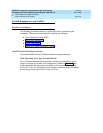
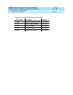
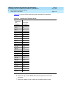
Table 2-1. Sneak Fuse Panel Ordering Information
Description Comcode
157B Connecting Block 403613003
SCP-110 Protector 406948976
507B Sneak Current Fuse Panel 107435091
220029 Sneak Current Fuse 407216316