


DEFINITY Enterprise Communications Server Release 6
Installation and Test for Multi-Carrier Cabinets
555-230-112
Issue 5
May 1998
Install Telecommunications Cabling
Page 2-5Installation Requirements
2
Installation Requirements
Sneak Fuse Panels and Emergency Transfer Units
Approximately 8 inches (20 cm) of horizontal wall space is required for each
column of sneak fuse panels. Up to 25 connector pairs can be protected by each
panel. Horizontal wall space must also be provided for emergency transfer units.
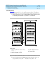
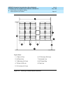
110-Type Hardware
The trunk/auxiliary field and the distribution field are mounted on the same wall.
Each 110P-type terminal block is 8.5 inches (21.6 cm) wide. Vertical patch cord
troughs are 5.31 inches (13.4 cm) wide and horizontal patch cord troughs are 23
inches (58.4 cm) wide.
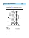
Each 110A-type terminal block is 10.81 inches (27.4 cm) wide; however, no
horizontal patch cord troughs are used and the blocks are shorter than
110P-type terminal blocks. This allows the 110A-type terminal blocks to be
stacked. Therefore, the 110A-type hardware requires less space than the
110P-type hardware on a per-station basis.
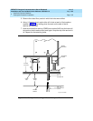
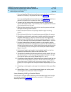
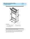
Cable Slack Manager
A Cable Slack Manager is 32 inches (81.3 cm) wide. The quantity of which is
determined by dividing the total length of the MDF in inches (cm) by 32 (81.3). A
partial number of 0.4 or less should be rounded down, and a partial number of
0.5 or more should be rounded up (for example: 2.4 = 2 cable slack managers
and 2.5 = 3 cable slack managers).
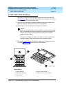
NOTE:
Cable clamps are required in installations with cable slack managers. At
the rear of the cabinets, on each rear ground plate, install 2 cable clamps
using the screws provided. These clamps hold the 25-pair input/output or
MDF cables in place.