


DEFINITY Enterprise Communications Server Release 6
Installation and Test for Multi-Carrier Cabinets
555-230-112
Issue 5
May 1998
Install Telecommunications Cabling
Page 2-44Label the Main Distribution Frame
2
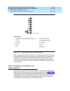
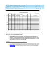
Administration Terminals
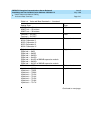
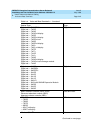
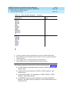
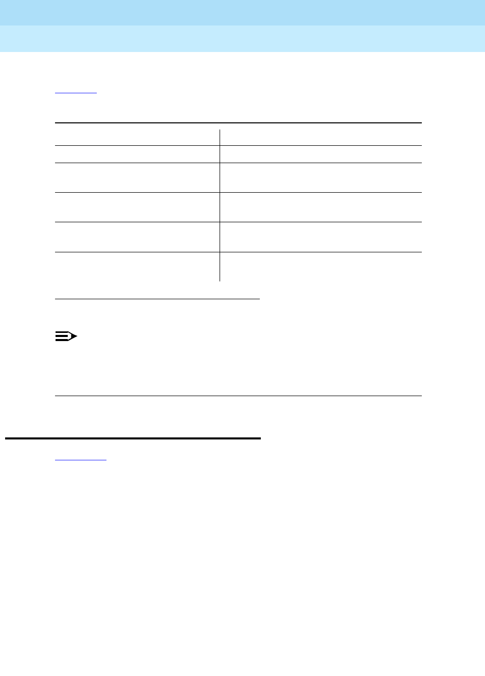
Tab le 2- 5 lists the administration terminals that can be connected to the system.
NOTE:
The 715 BCS (406803148 and 406803155), has a 6-pin mini-DIN keyboard
connector. The 2900/715 BCS (4073113881 and 407313899), has a 6-pin
RJ-11 keyboard jack located on the side of the terminal.
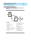
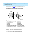
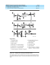
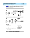
Label the Main Distribution Frame
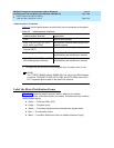
Figure 2-24 shows the graphic symbols used on labels for the system,
cross-connections, information outlets, and cables. The labels are color-coded to
identify system wiring:
■ Green — To Central Office (CO)
■ Purple — To system ports
■ Yellow — To auxiliary equipment and miscellaneous system leads
■ Blue — To information outlets
■ White — From Main Distribution Frame to satellite locations (3-pair)
1. The keyboards and terminals are interchangeable when an adapter cable is used.
Table 2-5. Administration Terminals
Administration Terminal Application
510D Remote administration
610D, 513, 610, 615, 715
1
BCT,
4410, 4425, and VT220
Management Terminal: administration and
general purpose
515 Business Communications
Terminal (BCT)
Remote administration, general purpose
615 Management Terminal Management Terminal system
administration and maintenance terminal
715 BCS, 2900/715 BCS, and 715
BCS-2 Management Terminal
Management Terminal system
administration and maintenance terminal