


DEFINITY Enterprise Communications Server Release 6
Installation and Test for Multi-Carrier Cabinets
555-230-112
Issue 5
May 1998
Install and Wire Telephones and Other Equipment
Page 5-461145B Power Supply
5
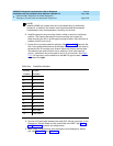
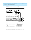
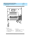
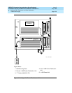
Wall-Mounting Plates
The top plate is used for mounting the back-up battery. The bottom plate is used
to mount the power supply and distribution units. The plates can be rack-
mounted using standard rack-mounting brackets.
1. Locate 1 plate directly below the other such that the AC power cord (6.5
feet or 2 meters) reaches the electrical outlet from a power supply
mounted on the bottom plate. Both plates should be located so the raised
letters are right side up.
NOTE:
A maximum of 4 power supplies can be powered from 1 dedicated
110 VAC, 20 amp (or 230 VAC, 15 amp) feeder. Use only unswitched
receptacles (receptacles not connected to a wall switch).
2. Secure the wall mounting plates to a standard 3/4 inch (2 cm) thick
plywood mounting board. Each mounting plate comes with four #10 x
1/2-inch wood screws.
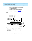
3. The 1145B Power Supply is snap-fit onto the bottom wall mounting plate
without tools.
4. An installer-provided insulated ground wire, 16 AWG (1.5 mm
2
) or greater,
is required to connect the power supply frame ground lug to an approved
ground. The frame ground screw is located next to the AC receptacle, to
the left of the unit.
5. Mark the Unit Number and Connectivity information on the front label next
to the LEDs.