


DEFINITY Enterprise Communications Server Release 6
Installation and Test for Multi-Carrier Cabinets
555-230-112
Issue 5
May 1998
Install and Connect Cabinets
Page 1-33Fiber Optic Interconnect Cabling
1
Critical Reliability
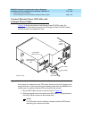
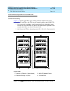
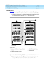
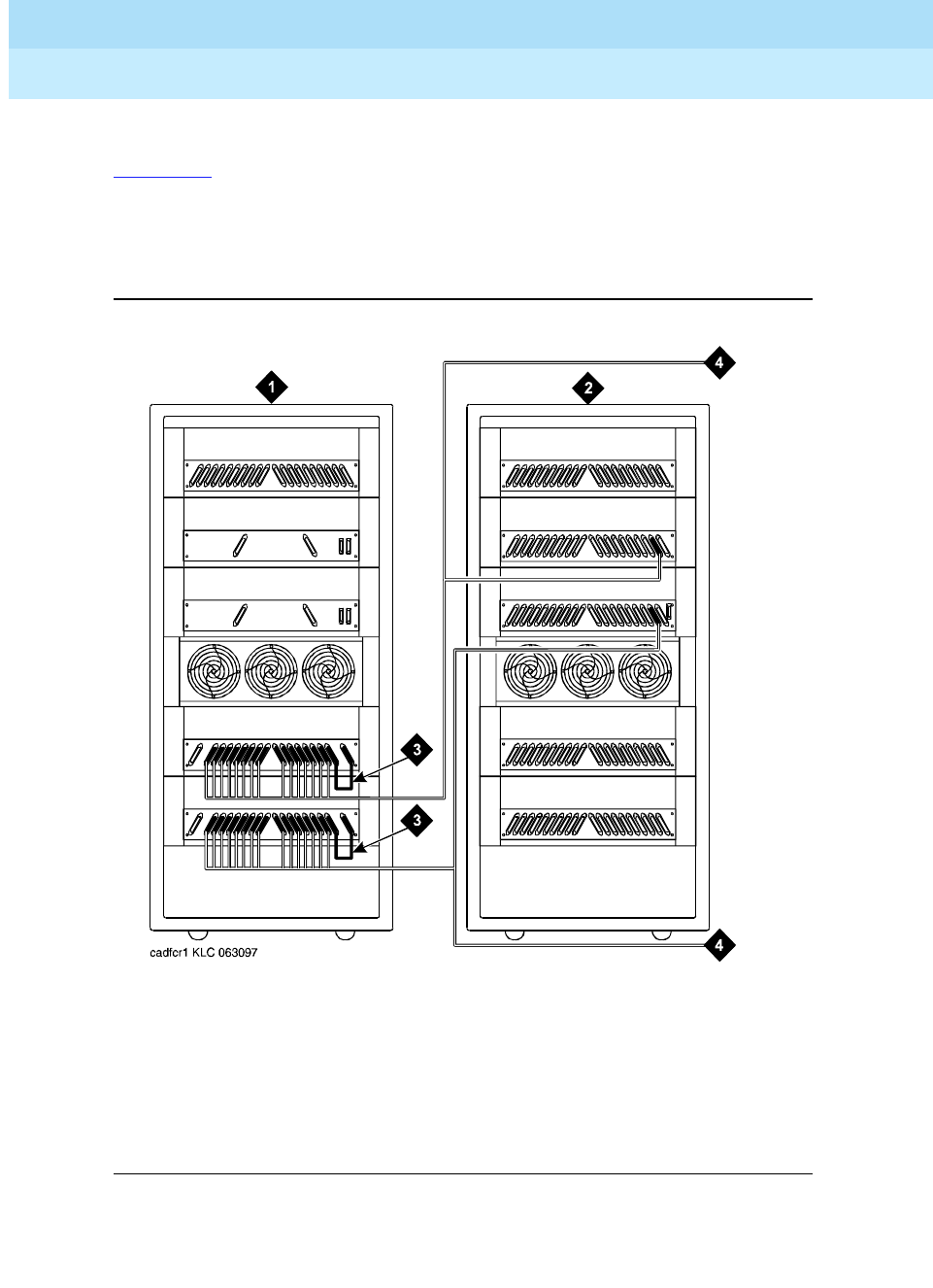
Figure 1-13 shows typical fiber optic cabling between cabinets. The cable
between port slots 1 and 2 on each switch node is a metallic cable (H600-278).
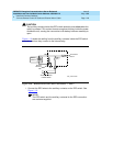
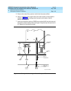
1. Connect the 2 groups of 1 to 15 cables between the PPN and each EPN in
an alternating port slot order: 20, 3; 19, 4; 18, 5; and so forth.
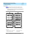
Figure 1-13. Critical-Reliability CSS-Connected with 1 Switch Node
2. Both connections from each EPN must go to the same slot number. For
example: EPN cabinet 2, 2A1 to 1E3 and cabinet 2, 2B2 to 1D3.
Figure Notes
1. Cabinet 1 (PPN with 1 Duplex Switch
Node)
2. Cabinet 2 through 16 (EPN)
3. H600-278 Metallic Cable
4. To other EPNs