


DEFINITY Enterprise Communications Server Release 6
Installation and Test for Multi-Carrier Cabinets
555-230-112
Issue 5
May 1998
Install Telecommunications Cabling
Page 2-48Patch Cord/Jumper Installation and Administration
2
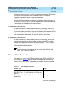
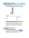
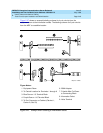
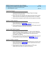
Figure 2-27 shows an example labeling scheme for 4-pair circuits from the
equipment room to the information outlets. The labeling scheme for 3-pair circuits
from the MDF to a satellite location.
Figure 2-27. Example 4-Pair Labeling to Information Outlet
Figure Notes:
1. Equipment Room
2. To Central Location for Terminals 1 through 6
3. Blue Row on 110 Terminal Block
4. Purple Row on 110 Terminal Block
5. To Port Connector on Cabinet (Cabinet 1,
Carrier A, Slot 03)
6. 258A Adapter
7. D-Inside Wire Cut Down
to Connecting Block
8. Information Outlet
9. Voice Terminal
crdf4pr CJL 102996