


DEFINITY Enterprise Communications Server Release 6
Installation and Test for Multi-Carrier Cabinets
555-230-112
Issue 5
May 1998
Install and Connect Cabinets
Page 1-25Connect Remote Power Off Cable and External Alarm Cable
1
Connect Remote Power Off Cable and
External Alarm Cable
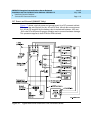
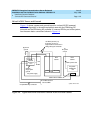
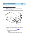
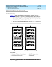
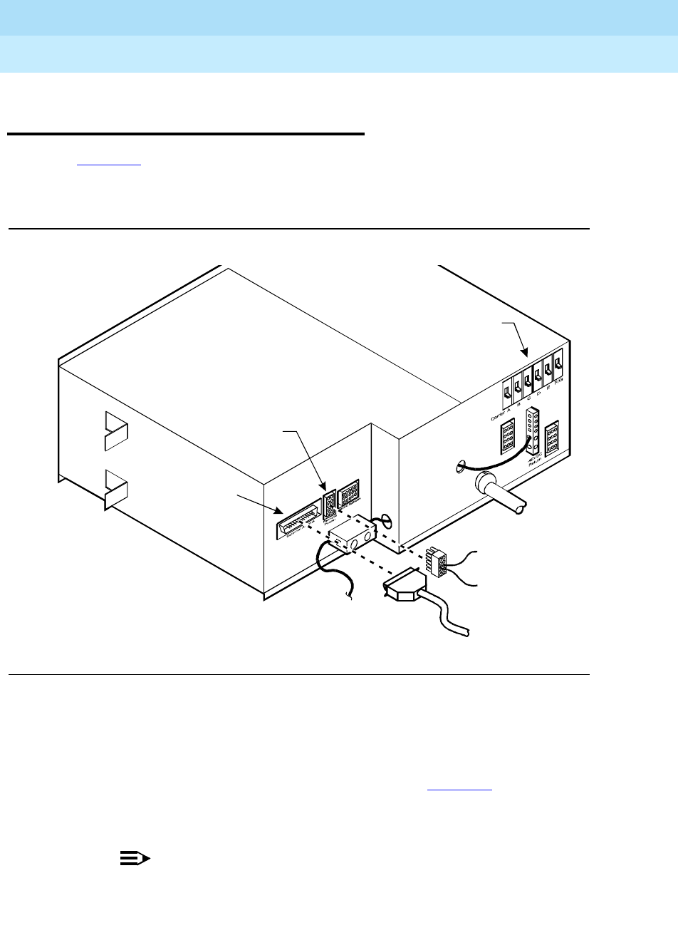
Figure 1-9 shows the location of the Remote Power Off (RPO) cable. The
opposite end of the cable connects to the Emergency Power Off (EPO) switch
located outside of the equipment room.
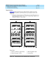
Figure 1-9. Remote Power Off Cable Connections — Part 1
Even though the equipment room EPO switch disconnects main AC power to the
equipment room, it cannot disconnect the battery power from the J58890CH. An
auxiliary set of contacts inside the EPO are used for this function.
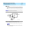
1. Plug the RPO cable into the connector shown in Figure 1-9
.
2. Route the opposite end of the wires to the EPO switch. The opposite end
of the RPO cable connects to the internal relay.
NOTE:
The EPO switch and the auxiliary contacts (inside the EPO switch
assembly) are customer-provided.
Connect RPO
cable here (J21)
Connect external
alarm cable here
(J18)
Carrier
circuit
breakers
psdf002CJL 081596
External
alarmcable
Pin 6 (-RPO)
Pin 2 (+RPO)