


DEFINITY Enterprise Communications Server Release 6
Installation and Test for Multi-Carrier Cabinets
555-230-112
Issue 5
May 1998
Cable Ductwork
Page C-10
C
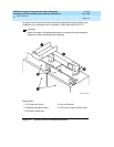
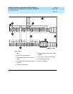
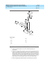
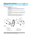
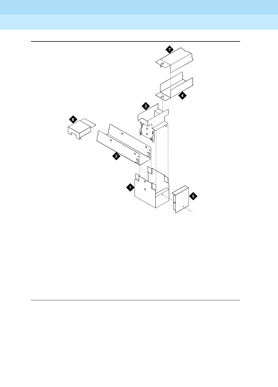
Figure C-5. Assembly of Cross-Aisle Shielded Ducts
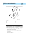
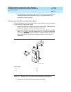
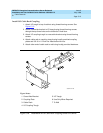
2. Install cross-aisle troughs on any other cabinets requiring such
connections.
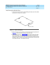
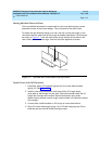
3. If there is no trough ("G") to install in one end of the cross-aisle riser ("C"),
press a cross-aisle shielded end cap ("F") on the unused end of the riser.
Unlike earlier ductwork, the endcap fits either end of the cross-aisle riser.
The side walls of the end cap go outside the walls of the riser. The ears on
the bottom of the end cap go outside of the riser’s bottom plate, and the
bottom plate of the end cap goes inside of the riser’s bottom plate.
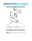
4. Route the appropriate cables between the cabinets just connected.
Figure Notes
1. A
2. B
3. C
4. G
5. E
6. F
7. H
xductcip KLC 071796