


DEFINITY Enterprise Communications Server Release 6
Installation and Test for Multi-Carrier Cabinets
555-230-112
Issue 5
May 1998
Install and Connect Cabinets
Page 1-4Install System Cabinets
1
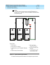
Position the Auxiliary Cabinet (Optional)
1. Position the Auxiliary cabinet next to the PPN cabinet (or EPN cabinet, if
installed). The location of equipment inside the Auxiliary cabinet is
specified in the Customer Service Document (CSD).
2. If earthquake protection is required, skip to ‘‘
Earthquake Protection
Installation’’ on page 1-34. Return to this section when finished.
3. If earthquake protection is not required, level the cabinets and adjust and
lock the cabinet stabilizing bolts to keep the cabinet from moving.
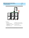
Install Auxiliary Cabinet Equipment
The Auxiliary cabinet allows for carrier, 23-inch (58.4 cm) rack, or panel
mounting of hardware. The following equipment is furnished with the cabinet.
■ Fuse panel — Distributes -48 VDC power to fused cabinet circuits
■ Power receptacle strip — Provides switched and unswitched 120 VAC
receptacles
■ DC connector block — Required when Auxiliary cabinet is powered by an
external DC source
■ AC to DC power supply — Converts AC power provided by the AC power
strip switched outlet to the required DC voltage
1. Install equipment inside the cabinet as specified in the CSD. The following
optional equipment can be installed:
■ Audichron H9040 Wake-Up Announcement System
■ 909A/B Universal Coupler
■ 7400 Series Data Modules
■ Z77A Multiple Data Mounting
■ Fan Assembly — Requires 120 volt AC power
■ COMSPHERE 3000-series modems
■ External Channel Service Unit (CSU) — 1 is required for each T1
carrier link
■ PagePac Paging System — 3 models are available. All PagePac
models require 120 VAC power.