


DEFINITY Enterprise Communications Server Release 6
Installation and Test for Multi-Carrier Cabinets
555-230-112
Issue 5
May 1998
Install Telecommunications Cabling
Page 2-38Station Circuit Distribution from Equipment Room
2
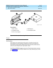
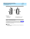
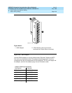
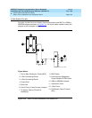
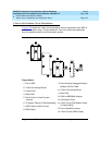
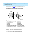
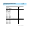
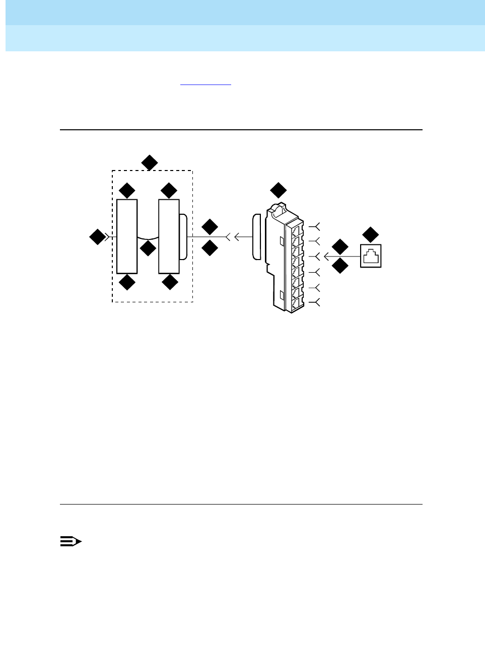
Three-pair circuits can also be run directly from the equipment room MDF to a
356A adapter as shown in Figure 2-23
. Four-pair station cables connect the
adapter to the information outlets. Four-pair station cables can be run directly
from a satellite location to the information outlets as previously described.
Figure 2-23. 3-Pair to 4-Pair Circuit Distribution and Connectivity
NOTE:
Bridged taps are not allowed on any part of the station wiring.
Figure Notes:
1. Part of Main Distribution Frame (MDF)
2. 3-Pair Connecting Blocks
3. Purple Field
4. Blue Field
5. Patch Cord or Cross-Connect Jumpers
6. To System Cabinet (3-Pair Modularity)
7. B25A Cable
8. 3-Pair Circuits
9. 356A Adapter
10. Information Outlet
11. 3-Pair Circuit in 4-Pair Wire
12. DIW Station Cable (D-Inside
Wire)
8
7
1
9
10
11
12
r758533a CJL 031196
2 2
43
6
5